Diagnosis
Before you begin you should have a good idea-or at least a plausible theory- about the nature of the problem. The diagnostic techniques described in Section 4 indicate whether or not major work is in order and, when supplemented by oil analysis, will suggest which class of parts-rings, gears, soft metal bearings, and so on-are wearing rapidly.
Test/analysis data, combined with a detailed operating history, should fairly well pinpoint the failure site (cylinder bore, crankshaft bearings, accessory drive, and the like). But analysis should not stop with merely verbal formulations. For example, it’s hardly meaningful to say that a bearing or a piston ring set has "worn out" or "overheated." One should try to identify what associated failure or special operating condition selected those parts to fail. City-bus wheel bearings are a good example of the selection process; experience shows that the right front bearings tend to fail more often than those on the left. Traces of red oxide in the lubricant suggest that failure comes about because of moisture contamination, (i.e., water splash), which is more likely to occur on the curb side of the vehicle.
Once the mechanic understands the failure mechanism, it might be possible to correct matters by performing more frequent maintenance, upgrading parts quality, or modifying operating conditions.
Rigging
FIG. 2 illustrates the proper lifting tackle for a large engine. Note how the spreader bar and adjustable crossheads keep the chains vertical to hook loads.
The engine shown incorporates lift brackets; less serious engines do not, and the mechanic is left to his own devising. In general, attachment points should straddle the center of gravity of the engine in two planes, so that it lifts horizontally without tilting.
Chains must clear vulnerable parts, such as rocker covers and fuel lines. Lift brackets made of 3 / 8 in. flame-cut steel plate are the ideal, but forged eyebolts (available from fastener supply houses) are often more practical. A spreader bar will eliminate most bending loads, but there are times when chain angles of less than 90 degr. cannot be entirely avoided. Reduce the bending load seen by the eyebolt with a short length of pipe and heavy washer, as shown in FIG. 3.
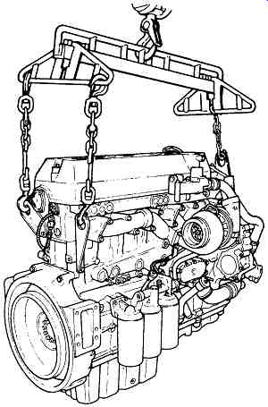
FIG. 2 A proper engine sling is a necessity. Detroit Diesel
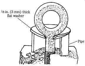
FIG. 3 Hardened eyebolts occasionally must be used in lieu of lift brackets.
Bolts should thread into a minimum depth of three times the diameter and should
be rein forced as shown to limit bending forces.
In no case should chains be bolted directly to the block without the intermediary of a bracket or eyebolt. Nor is multistrand steel cable appropriate for this kind of knock-about service.
FIG. 4 illustrates a minimal engine stand, suitable for engines in the 600-lb. class. Better stands usually attach at the side of the block (as opposed to the flywheel flange) and can be raised and lowered.
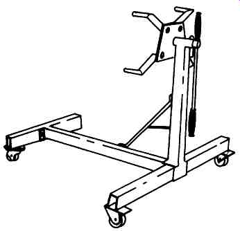
FIG. 4 Purchase the best engine stand you can afford, with a weight capacity
that provides a comfortable safety margin.
Note: A mechanic can get into trouble with one of these revolving-head stands.
Inverting an assembled engine with the turbocharger intact can dump oil from the turbocharger sump into one or more cylinders. Subsequent attempts to start the flooded engine might result in bent connecting rods or worse.
Special considerations
Mechanics who are knowledgeable about gasoline engine repair will find them selves doing familiar things, but to more demanding standards. Diesel engines are characterized by:
Close tolerances
Close tolerances impose severe requirements in terms of inspection, cleanliness, and torque limits. Tolerance stack-unacceptable variations in dimension of assemblies made up of components that fall on the high or low ends of the tolerance range-becomes a factor to contend with. As delivered from the factory, some engines employ a selective assembly of bearing inserts and pistons.
High levels of stress Hard-used industrial engines are subject to structural failures, a fact that underscores the need for careful inspection of crankshafts, main-bearing webs and caps, connecting rods, pistons, cylinder bore flanges, harmonic balancers, and all critical fasteners.
Inflexible refinishing and assembly norms
Stress and close tolerances give little latitude for quick fixes and, unless contradicted by hard experience, factory recommendations should be followed to the letter.
Special features
While nothing in four-cycle diesel crankcases can be considered uniquely diesel, some features of these engines might be unfamiliar to most gasoline-engine mechanics. Nearly all engines employ oil-cooled pistons.
This is accomplished with rifle-drilled connecting rods or, as is more often the case today, by means of oil-spray tubes, or jets, which direct a stream of oil to the piston undersides ( FIG. 5). Jets that bolt or press into place must be removed for cleaning and usually require alignment.
Diesel engines often employ removable cylinder sleeves, pressed or slipped into counterbores and standing proud of the fire deck. Installation is quite critical and special honing techniques are usually recommended.
Another difference is the apparent complexity of power transmission, which on some engines can have an almost baroque ornamentation. FIG. 6 illustrates the bull gear/idler gear and accessory drive gear constellation on the DDA Series 60 engine. Belt drives may be hardly less imposing, as the drawing in FIG. 7 indicates.
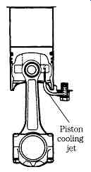
FIG. 5 Spray jet aiming is critical. Ford Motor Co.
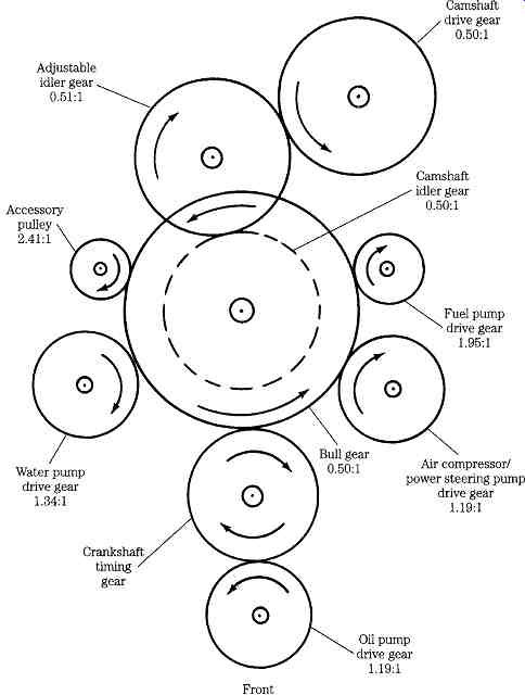
FIG. 6 Detroit Diesel engines are known for their sophisticated gear trains.
In fact, this complexity is more illusory than real. One merely comes to terms with timing marks, deals with one component at a time, and builds the power train brick by brick. Of course, the work goes more slowly than it would on a simpler engine, and the parts cost can be daunting, especially when gears need to be replaced.
The power train can include one or more balance shafts, a technology that is rarely seen on spark ignition engines (the Mitsubishi/Chrysler 2.6L is one of the few exceptions).
FIG. 8 illustrates the balance shaft configuration for a four-cylinder in-line engine. Two contra-rotating shafts, labeled Silent shafts in the drawing, run at twice crankshaft speed to generate forces that counter the "natural" vibration of the engine.
Engines of this type employ single-plane, two-throw crankshafts. Pistons 1 and 4 move in concert, as do pistons 2 and 3. When pistons 1 and 4 are down, 2 and 3 are up. Consequently, vertical forces generated by pistons 1 and 4 (indicated by the dotted line in FIG. 9) oppose the forces generated by the center pair of pistons (represented by the fine line). These vertical forces, known as primary shaking forces, almost cancel and can be ignored.
Secondary forces pose a more serious problem. Created by connecting-rod angularity and by piston acceleration during the expansion stroke, these forces tend both to rotate the engine around the crankshaft centerline and to shake the engine vertically. Magnitude increases geometrically with rpm, to produce the dull rattle characteristic of in-line four-cylinder engines at speed.
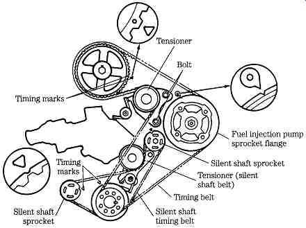
FIG. 7 Ford 2.3L turbocharged diesel makes extensive use of toothed belts.
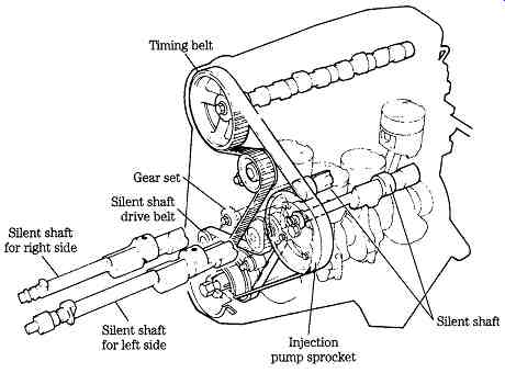
FIG. 8 Balancing secondary forces requires two counterweighted shafts running
at twice crankshaft speed. Ford Motor Co.
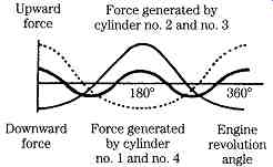
FIG. 9 Primary forces in in-line four-cylinder engine very nearly balance.
In an opposed four, with two crankshaft throws in the same plane 180° apart,
balance is nearly perfect. A slight rocking couple, imposed by the offset between
paired connecting rods on each crankshaft throw, does, however, exist. Ford
Motor co.
Secondary vertical and rolling forces are neutralized by deliberately induced imbalances in the balance shafts. FIG. 10 diagrams the sequence of countervailing forces through full crankshaft revolution (two balance shaft revolutions).
Detroit Diesel approaches the question of balance differently on its two-cycle engines. Here the concern is to balance the rocking couple created by crankpin offset.
Such couples exist unless all pistons share the same crankpin, as For example, in a radial engine with one connecting rod articulated from a central master rod. DDA practice is to use a counterweight can and balance shafts driven at crankshaft speed through counterweighted gears. In other words, each shaft has two sources of imbalance, one integral with the drive gear and the other in the form of a bob weight on the free end of the shaft. Shaft counterweights and shaft gear weights are disposed radially to create a countervailing couple, which acts in opposition to the crankshaft induced couple. No attempt is made to balance secondary forces.
From a mechanic's point of view, the critical aspects of this technology are the shaft bearings, which are subject to severe radial loads and catastrophic failure. In some cases, bearing bosses must be sleeved before new bearings can be installed.
Give the oiling circuit close scrutiny; endemic bearing can justify modifications to increase the rate of oil flow. And of course it’s necessary to time the shafts relative to each other and to the crankshaft.
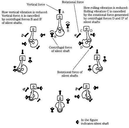
FIG. 10 Balance shaft/crankshaft forces during a complete engine revolution.
Ford Motor co.
Fasteners
Contemporary foreign and, to a great extent, American engines are built to the metric ISO (International Standards Organization) standards, developed from the European DIN. For most practical purposes DIN and ISO fasteners interchange. A JIS standard also exists, but most Japanese fasteners made since the early 1970s follow the ISO pattern. Some JIS bolts interchange (although head dimension can differ) with those built to the current standard; others make up just enough to strip out.
Few American manufacturers remain wedded to the inch standard, although leaving is hard to do. Engines come off the line with both ISO and fractional fasteners, inch-standard pipe fittings and metric fuel systems.
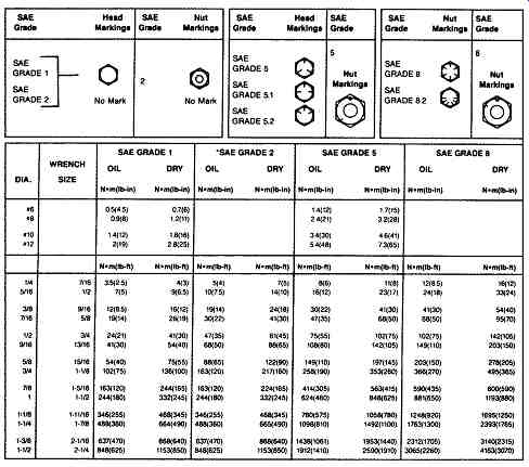
FIG. 11 Inch cap screw torque values. 1990. Deere & Co. All rights reserved
ISO fasteners are classed by nominal bolt diameter in millimeters and thread pitch measured as millimeters between adjacent thread crests. Thus, a specification might call for an M8 _ 1.0 cap screw or stud. Wrench size markings reflect bolt diameter, not the flat-to-flat distance across the screw head. Yield strength is indicated by a numeric code embossed on the screw head. The higher the number, the stronger the cap screw.
Metric hex nuts often carry the same numerical code, but this practice is not universal.
Figures 11 and 12 supply identification data and suggested torque limits for U.S. and metric cap screws. Torque limits were calculated from bolt yield strength ratings, and do take into account the effects of clamping forces on vulnerable parts or gaskets. Consequently, these values should not be used when the engine manufacturer provides a different torque limit or tightening procedure for a specific application.
Tighten plastic insert-- or crimped- steel-type locknuts to about half the amount shown in the charts; toothed- or serrated-type locknuts receive full torque. Replace fasteners with the same or higher grade, except in the case of shear bolts, which are grade specific. When substituting a better-grade fastener, torque it to the value of the original.
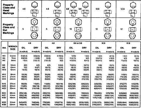
FIG. 12 Metric cap screw torque values. 1990. Dears & Co. All rights
reserved
Prev. | Next
Home top
of page Similar articles