Most diesels have open manifolds without the restriction imposed by a throttle plate.
As a result, these engines ingest about 2.5 ft^3 of air per horsepower. Much of the air merely cycles through the engine without taking part in combustion. But atmospheric air, even at its most pristine, contains mineral dust and other solids that, unless removed, result in rapid upper cylinder wear. Research has shown that the most destructive particulates in the air-inlet system are between 10 and 20 µm in diameter. A micron is one millionth of a meter or 4/100,000 in.
Air cleaners
The ideal air cleaner would trap all solids, regardless of size. Unfortunately, such a device does not exist, at least in practical form. Some particulates get through, which is why engines tend to wear rapidly in dusty environments, no matter how carefully maintained.
Construction
Older engines are often fitted with oil-bath filters that combine oil-wetted filtration with inertial separation ( FIG. 1). Air enters at the top of the unit through the precleaner, or cyclone. Internal vanes cause the air stream to rotate, which tends to separate out the larger and heavier particulates. The air then passes through the central tube to the bottom of the canister, where it reverses direction. Some fraction of the remaining particulates fail to make the U-turn and end in the oil reservoir. Most of those that remain are trapped in the oiled mesh.
These devices depend, in great part, upon the velocity of the incoming air to centrifuge out heavier particles. At low engine speeds, the particles remain in the air stream, and filtration depends solely upon the oil-wetted mesh. Under ideal circum stances filtering efficiency is no more than 95% and, in practice, can be much less.
If overfilled, subjected to high flow-rates, or tilted much off the horizontal, oil-bath cleaners bleed oil into the intake manifold. The oil can plug the aftercooler and raise exhaust temperatures enough to cause early turbocharger failure.

FIG. 1. Oil-bath air cleaner with a centrifugal precleaner.
These units have a peak efficiency of about 95%, which falls off rapidly at low engine speeds.

FIG. 2. A single-stage paper-element air cleaner of the type used for automotive
and marine applications. Two-stage paper filters achieve efficiencies of as
high as 99.99%, which sounds impressive, but air-borne abrasives continue to
be the primary cause of engine wear. Marine Engine Div., Chrysler Corp.
Figure 2 shows a replaceable paper-element filter of the type used on automobiles and light trucks. When used for industrial engines, the paper element is often combined with a prefilter and a centrifugal precleaner. At their most sophisticated, paper-element filters can have an efficiency of 99.99%. Efficiency improves when the filter is lightly impacted with dust. Engines operated in extremely dusty environments also benefit from an exhaust-powered ejector mounted upstream of the filter.
The filter should be mounted horizontally on the manifold to reduce the possibility of dirt entry when the element is changed. Filters that mount vertically, such as the one shown in FIG. 2, should include a semi-permanent safety element below the main filter. This element functions to trap dust when the filter is removed for servicing.
All engines should have some sort of filter monitoring device that, if not sup plied by the manufacturer, can be fabricated by the simple expedient of plumbing a vacuum gauge immediately downstream of the filter. When new, paper-element filters impose a pressure drop of about 6.0 in./H2O and the inlet ducting usually adds about 3.0 in./H2O. Engine performance falls off noticeably when the total system pressure drop exceeds 15 in./H2O.
Service the filter only when the air-restriction indicator trips, since each time the element is removed some dust enters the system. Before removing the element wipe off all dust from the inside of the filter housing. Do not blow out paper elements with compressed air: a tear in the element, so small that it may not be visible to the eye, exposes the engine to massive amounts of dust intrusion.
And before we leave the subject, it should be remarked that "high-performance" filters can provide marginal power increases by reducing pumping losses. But the reduction in pressure drop often comes at the cost of reduced filtration efficiency.
Any air filter worthy of its name should have its efficiency certified by a third party under the protocols of the SAE air cleaner test code J726.
Rebuilt engines almost always have shorter lives than new engines. For years it was believed that factory inspection and assembly procedures gave new engines the edge. But evidence is accumulating that abrasives entering from leaks in the flexible tubing couplings downstream of the filter are the culprit ( FIG. 3a). These couplings, which see boost temperatures of 300°-400°F (149°-204°C), harden with age and are rarely replaced. Nor is it possible to detect leaks by external inspection of the tubing and hose couplings. However, the presence of leaks will be revealed by streaks in the dust film that collects on inlet-tubing inner diameters (IDs). The origin of the streak marks the point of dirt entry.
Flexible couplings should be replaced periodically and as inexpensive insurance for rebuilt engines. Secure the coupling with SAE type F clamps-not worm-gear plumber's clamps-that provide a 360° seal.
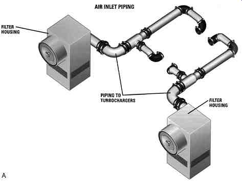
FIG. 3A. Elastomer tubing couplings downstream of the filter are a major and
nearly always overlooked source of dust entry. Caterpillar Inc.

FIG. 3B. John Deere 6068T turbocharged engine. One of the appeals of turbocharging
is its apparent simplicity. In this instance, a 25-lb turbocharger boosted
output to 175 hp for a gain of 45 hp over the naturally aspirated version of
the same engine. Torque went from 335 lb-ft to 473 lb-ft.
Turbochargers
A turbocharger is an exhaust-powered supercharger, that unlike conventional super chargers, has no mechanical connection to the engine (Figs. 3b and 4). The exhaust stream, impinging against the turbine (or "hot") wheel, provides the energy to turn the compressor wheel. For reasons that have to do with the strength of materials, turbo boost is usually limited to 10 or 12 psi. This is enough to increase engine output by 30-40%.
Turbocharging represents the easiest, least expensive way to enhance performance. It is also something of a "green" technology, because the energy for compression would otherwise be wasted as exhaust heat and noise ( FIG. 5). On the other hand, the interface between sophisticated turbo machinery, turning at speeds as great as 140,000 rpm and at temperatures in excess of 1000°F, and the internal combustion engine is not seamless.
Unless steps are taken to counteract the tendency, turbochargers develop maxi mum boost at high engine speeds and loads. The turbine wheel draws energy from exhaust gas velocity and heat, qualities that increase with piston speed and load. The compressor section behaves like other centrifugal pumps, in that pumping efficiency is a function of impeller speed. At low speeds, the clearance between the rim of the impeller and the housing shunts a large fraction of the output. At very high rotational speeds, air takes on the characteristics of a viscous liquid and pumping efficiency approaches 100%. In its primitive form, a turbocharger acts like the apprentice helper, who loafs most of the day and, when things get busy, becomes too enthusiastic.
Another innate, but not necessarily uncorrectable, characteristic of turbocharged engines is the lag, or flat spot, felt during snap acceleration. Perceptible time is required to overcome the inertia of the rotating mass. By the same token, the wheels continue to coast for a few seconds after the engine stops.

FIG. 4 A turbocharger is an exhaust-driven centrifugal pump, operating at six-figure
speeds and typically generating 10-12 psi of supercharge.

FIG. 5 Turbocharger heat balance chart. Note that even with turbocharging 30%
of the fuel energy goes out the exhaust.
Background
The exhaust-driven supercharger was first demonstrated in 1915, but remained impractical until the late 1930s, when the U.S. Army, working closely with General Electric, developed a series of liquid-cooled and turbocharged aircraft engines. The expertise in metallurgy and high temperature bearings gained in this project made GE a leader in turbocharging and contributed to its success with jet engines.
As applied to aircraft, turbocharging was a kind of artificial lung that normalized manifold pressure at high altitudes. A wastegate deflected exhaust gases away from the turbine at low altitudes, where the dense air would send manifold pressures and engine power outputs to dangerously high levels. In emergencies, P-51 pilots were instructed to push their throttles full forward, an action that broke a restraining wire, closed the wastegate, richened the mixture, and initiated alcohol injection for a few seconds of turboboost. The broken wire was a telltale sign, signaling the ground crew to rebuild the engine.
Turbochargers continue to be used on reciprocating aircraft engines and enjoy some currency in high performance automobiles, thanks to electronic controls that minimize detonation. But diesel engines are the real success story.
Turbocharging addresses the fundamental shortcoming of compression ignition, which is the delay between the onset of injection and ignition. That delay, terminated by the sudden explosion of puddled fuel, results in rapid cylinder pressure rise, rough running and incomplete combustion with attendant emissions. Turbocharging (and supercharging generally) increase the density of the air charge. Ignition temperature develops early during the compression stroke and coincides more closely with the onset of injection. Fuel burns almost as quickly as delivered for a smoother running, cleaner, and more economical engine.
Applications
Depending on how it is accomplished, turbocharging can have three quite distinct effects on performance. If no or little additional fuel is supplied, power output remains static, but emissions go down. Surplus air lowers combustion temperatures and provides internal cooling. Such engines should be more durable than their naturally aspirated equivalents.
The high-boost/low-fuel approach to turbocharging is limited to large stationary and marine plants. Makers of small, high-speed engines are more concerned with maximum power or mid-range torque.
Supplying additional fuel in proportion to boost yields power, which can translate as fuel savings for engines that run under constant load. Some gains in fuel efficiency (calculated on a hp/hour basis) accrue from turbocharging, but the real advantage comes about when high supercharge pressures allow for lower piston speeds. Large marine engines, developing a 1000 hp and more per cylinder, use this approach to achieve thermal efficiencies of 50%. On a more familiar scale, the naturally aspirated International DT-414 truck engine produced 157 hp at 3000 rpm. The addition of a large turbocharger boosted output to 220 hp, for a gain of 40%. Once in the fairly narrow power band, the trucker could save fuel by selecting a higher gear.
The third approach is more characteristic of automotive and light truck engines, which operate under varying loads and rarely, if ever, develop full rated power.
What is wanted is torque?
The Navistar 7.3L, developed for Ford pickups and Econoline vans, is perhaps the best demonstration of the way a turbocharger can be throttled for torque production. In its naturally aspirated form, the engine develops 185 hp at 3000 rpm and 360 ft./lb. of torque at 1400 rpm. A Garrett TC43 turbocharger boosts power output marginally to 190 hp; but torque goes up 17.8% to 385 ft/lb. In normal operation the wastegate remains closed, directing exhaust gases to the turbine, until 1400 rpm. At that point, which corresponds to the torque peak, the hydraulically actuated waste gate begins to open, shunting exhaust away from the turbine.
Serious applications of turbocharging, whether for peak power or mid-range torque, impose severe mechanical and thermal loads, which should be anticipated in the design stage. Insofar as they work as advertised, add-on turbocharger kits- which rarely involve more than a rearrangement of the plumbing-are a buyer beware proposition. The 7.9L is considered a very rugged engine in its naturally aspirated form. But turbocharging called for hundreds of engineering changes, including shot-peened connecting rods, oversized piston pins, Inconel exhaust valves, and special Zollner pistons, with anodized crowns.
Construction
Figure 6 illustrates an air-cooled Ishikawajima-Harima turbocharger of the type found on engines in the 100-150-hp range. The inset shows the water-cooled version of the same turbocharger, plumbed into the engine cooling system. All modern small-engine turbochargers follow these general patterns.
Floating bushings, located in the central bearing chamber, support the shaft.
These bushings, like the connecting rod bearings specified for the original Ford V-8, float on the ID and OD. Thus, bushing speed is half that of shaft speed, which is to say that the bushings can reach speeds of 60,000 or 70,000 rpm. A floating thrust bushing contains axial motion.
Also note the way the impeller wheels cantilever from the bushings, so that the masses of the rotating assembly are concentrated near the ends of the shaft. This "dumb-bell" configuration requires precise wheel balance and extremely accurate shaft alignment.
The bearing section is lubricated and cooled by engine oil, generally routed through external pipes or hoses. Shaft seals keep oil from entering the turbine and compressor sections.
The turbocharger is usually the last component to receive oil pressure and might continue to rotate after the engine stops. To ensure an adequate oil supply to the bearings, operators should idle the engine for at least 30 seconds upon starting and for the same period before shutdown.
Wastegate
All turbocharger installations incorporate some form of boost limitation; other wise, boost would rise with load until the engine destroyed itself.
Turbocharger geometry, sometimes abetted by inlet restrictions and designed-in exhaust backpressure, limit boost on constant-speed engines. Automotive and light truck engines have surplus turbocharging capability for boost at part throttle. These applications employ a wastegate-a kind of flap valve-that automatically opens at a preset level of boost to shunt exhaust gas around the turbine.
Most wastegates are controlled by a diaphragm, open to the atmosphere on one side and to manifold pressure on the other ( FIG. 7). The Ford unit shown also incorporates a relief valve. Normally the wastegate opens at 10.7 psi; should it fail to do so, the relief valve opens at 14 psi and, because it is quite noisy, alerts the driver to the over-boost condition.

FIG. 6 Air- or water-cooled turbocharger of the type used on small Japanese
diesels. Water cooling may prolong bearing life and should reduce the coking
experienced during hot shut downs, when the turbocharger continues to rotate
after the engine stops.
Other wastegates are spring-loaded and usually include an adjustment, appropriately known as the "horsepower screw." As usually configured, tightening the screw increases available boost. Therefore, exercise restraint.
Test wastegate operation by loading the engine while monitoring rpm and manifold pressure. If the installation does not include a boost gauge, connect a 0-20 psi pressure gauge at any point downstream of the compressor. The diaphragm-sensing line (on units so-equipped) serves as a convenient gauge point. Note, however, that the gauge must be connected with a tee fitting to keep the wastegate functional. High gear acceleration from 2500 rpm or so should generate sufficient load to open the gate.
The control philosophy discussed in the preceding paragraphs implies that the turbocharger is used for power enhancement. When mid-range torque is the object, the wastegate opens early, at the engine speed corresponding to peak torque out put. Most of these applications employ computer-controlled wastegates, whose response is conditioned by manifold pressure, engine rpm, coolant temperature, and other variables. No generalized test procedure has been developed for these devices.

FIG. 7. Diaphragm-controlled wastegate and pressure-relief valve, as used in
on Ford 2.3L diesel engines.
Aftercoolers
Compressing air raises its temperature, which reduces change density and tends to defeat the purpose of supercharging. Sophisticated turbocharger installations include a heat exchanger, or aftercooler, between the compressor outlet and intake manifold. The cooling medium can be air, engine coolant, or-for marine applications-water. The plate and tube seawater-fed aftercooler used with the Yanmar 4LH-HTE boosts out put to 135 hp, or 30 hp more than an identical engine without aftercooling.
Air-cooled heat exchangers work most efficiently when mounted in front of the radiator. Engine coolant should be taken off at the pump discharge and returned to some point low on the water jacket.
Air-cooled units require little attention, other than an occasional dust off. Liquid cooled heat exchangers should be cleaned as needed to remove scale and fouling, and periodically tested by blowing low-pressure (25-psi maximum) air through the tubes. Water intrusion into the intake tract can be expensive.
Routine maintenance
The first priority is to obtain actual performance data, particularly with reference to turbocharger behavior. The full story would require a dynamometer to extract, but one can gain useful insight by observing the changes in manifold pressure under working loads that, at some point in the test, should be great enough to cause the wastegate to open. The rise in oil temperature and variations in crankcase pressure supply additional parts of the picture.
Do not operate a turbocharged engine unless the air cleaner (or spark arrestor) is in place and the intake-side ducting secure. The compressor acts as a vacuum cleaner, drawing in foreign, objects which will severely damage the unit and might cause it to explode. The troubleshooting chart ( Table 1) makes reference to coast-down speed.
If you feel it is necessary to observe compressor rotation, cover the turbocharger inlet with a screen to at least keep fingers and other large objects out of the mechanism.
When dismantling a turbocharger and related hardware, make a careful tally of all fasteners, lockwashers, and small parts removed. Be absolutely certain that all are accounted for before starting the engine. Immediately shut down the engine if the turbocharger makes unusual noise or vibrates.
Turbocharging (and supercharging generally) put severe stress on lubrication, air inlet, crankcase ventilation, and exhaust systems.
Lubrication system
Elevated combustion pressure contaminates the oil with blowby gases and pro motes oxidation by raising crankcase oil temperature. That fraction of the oil diverted to the turbocharger can undergo 80°F temperature rise in its passage over the bushings. Change lube oil and filter(s) frequently.
The cost and disposal problems associated with filters make reusable filters attractive for fleet operators. Racor, a division of Parker Hannifin, manufactures a series of liquid filters with washable, stainless-steel elements and a TattleTale light that alerts the operator when the filter needs to be cleaned.
Frequently inspect the turbocharger and its oiling circuitry for evidence of leaks that, if neglected, can draw down the crankcase.
========
Table 1. Turbocharger fault diagnosis Engine lacks power, black smoke in exhaust
[
Symptom
1. Insufficient boost 1 pressure; compressor wheel coasts to a 3 smooth stop when engine is shut down; turns easily by hand.
2. Insufficient boost 1 pressure; compressor wheel does not turn 2 or judders during coastdown; drags or binds when turned s by hand.
]
[
Probable causes
. Clogged air filter element.
. Restriction in air intake.
. Air leak downstream of compressor.
. Insufficient exhaust gas energy
• Exhaust leaks upstream of R turbocharger.
• Exhaust restriction downstream of turbocharger.
. Carbon accumulations on turbine-shaft oil seats.
. Bearing failure, traceable to:
• Normal wear.
• Insufficient oil.
• Excessive oil temp.
• Turbo rotating assy out of balance.
• Bad operating practices--application of full throttle upon startup and/or hot shutdown.
. Rotating assembly makes rubbing contact with case.
Leading causes are:
• Bearing failure (see above).
• Entry of foreign matter into R compressor.
• Excessive turbo speed.
• Improper assembly.
]
[
Corrective actions
Clean or replace element.
Remove restriction.
Repair leak.
Repair leak.
Remove restriction.
Disassemble, clean turbocharger and change oil and filter.
Rebuild turbo.
Rebuild turbo. Inspect oil supply/return circuit and repair as necessary to restore full flow.
Change engine oil and filter.
Rebuild turbo. Clean oil cooler (if fitted); change engine oil and filter.
Monitor oil temp.
Rebuild and balance turbo.
Rebuild turbo. Train operators.
A prelube system may extend turbo life in harsh operating environments.
Rebuild turbo. Determine cause of failure and correct.
Rebuild turbo. Inspect air cleaner and repair as necessary.
Rebuild turbo. Turbo rpm is a function of exhaust gas temperature (engine load). Check air filter for restrictions, bar over engine to verify that crankshaft rotates freely.
If necessary, adjust governor to reduce engine power output.
Repair turbo, review-service procedures.
]
Excessive oil consumption, blue or white exhaust smoke
[
Symptom
1. Condition may be accompanied by 2 oil stains in the inlet and/or outlet ducting, or, in extreme eases, by oil drips from the turbo charger housing.
Abnormal turbocharger
Symptom
1. Engine power output exhibits a w pronounced "flat spot" during acceleration. Fuel system appears to function normally.
Unusual noise or vibratio
Symptom
1. "Chuffing" noise, often most c pronounced during acceleration.
2. Knocking or squeal.
3. Speed-sensitive 1 vibration.
]
[
Probable cause
1. High restriction in the air inlet.
2. Worn turbocharger seals, R possibly associated with bearing failure and/or wheel imbalance.
Probable cause
. Carbon buildup on compressor wheel and housing.
Probable cause
1. Surging caused by restriction at compressor discharge nozzle.
1. Rotating elements in contact with housing because of bearing failure or impact damage.
1. Loose turbocharger mounts
2. Rotating elements in contact with housing.
3. Severe turbine shaft imbalance.
]
[
Corrective actions
Clean or replace filter element.
Repair turbo.
Corrective actions Disassemble and clean turbo.
Corrective actions Disassemble and clean turbo.
Replace or rebuild turbo.
Tighten Replace or rebuild turbo.
Rebuild and balance.
]
==========
Air inlet system
Dust particles, entering through a poorly maintained filter or through leaks in the ducting rapidly erode the compressor wheel. Leaks downstream of the compressor cost engine power and waste fuel.
Crankcase ventilation system
This system removes combustion residues and, in the process, subjects the crankcase to a slight vacuum. In normal operation, fresh air enters through the breather filter and crankcase vapors discharge to the atmosphere (pre-pollution engines) or to the intake side of the turbo compressor. The latter arrangement, known as positive crankcase ventilation (PCV) is the norm.
Under severe load, blowby gases accumulate faster than they can be vented and escape through the breather filter. These flow reversals, which occur more frequently in turbocharged engines, tend to clog the filter. Restrictions at the filter allow corrosive gases to linger in the crankcase. A partially functional filter can also pressurize the crankcase under the severe blowby conditions that accompany heavy loads. Oil seals and gaskets leak as a consequence.
Under light loads, reduced flow through the breather depressurizes the crankcase. Low crankcase pressures encourage oil to migrate into the turbocharger and collect in the aftercooler on engines with positive crankcase ventilation. Because oil is a fairly good thermal insulator, the efficiency of the aftercooler suffers. Tests of a Detroit Diesel engine, conducted by Diesel Research, Inc., established that oil migration resulting from a 40% efficient breather cost 6% of engine output. The engine in question had 4000 hours on the clock.
Exhaust system
Restrictions downstream of the turbine-crimped pipes, abrupt changes in direction, clogged mufflers-reduce turbo efficiency and, in extreme cases, represent enough load to induce boost. However, exhaust leaks between the engine and turbocharger are more typical. The pipe rusts out (especially if wrapped in insulation), fatigues, or cracks under the 1000°F-plus temperature. If OEM parts do not give satisfactory service, you might try calling a Flexonics applications engineer. The company makes a line of exhaust tubing, fitted with metal bellows to absorb thermal expansion.
Turbocharger inspection
The seven-step inspection procedure outlined here was adapted, with modifications, from material supplied by John Deere.
1. Turbo housing
Before disconnecting the oil lines, examine external surfaces of the housing for oil leaks, which would almost certainly mean turbo seal failure.
2. Compressor housing inlet and wheel
Inspect the compressor wheel for erosion and impact damage. Erosion comes about because of dust intrusion; impact damage is prima facie evidence of negligence. Carefully examine the housing ID and compressor blade tips for evidence of rubbing contact, which means bearing failure.
3. Compressor housing outlet
Check the compressor outlet for dirt, oil, and carbon accumulations. Dirt points to a filtration failure; oil suggests seal failure, although other possibilities exist, such as clogged turbo-oil return line or crankcase breather. Carbon on the compressor wheel might suggest some sort of combustion abnormality, but the phenomenon is also seen on healthy engines. I can only speculate about the cause.
4. Turbine housing inlet
Inspect the inlet ports for oil, heavy carbon deposits, and erosion. Any of these symptoms suggest an engine malfunction.
5. Turbine housing outlet and wheel
Examine the blades for impact damage.
Look for evidence of rubbing contact between the turbine wheel and the housing, which would indicate bearing failure.
6. Oil return port
The shaft is visible on most turbochargers from the oil return port. Excessive bluing or coking suggests lubrication failure, quite possibly caused by hot shutdowns.
7. Bearing play measurements--Experienced mechanics determine bearing condition by feel, but use of a dial indicator gives more reliable results. Note that measurement of radial, or side-to-side, bearing clearance involves moving the shaft from one travel extreme to another, 180° away ( FIG. 8A). Hold the shaft level during this operation, because a rocking motion would muddy the results. Axial motion is measured as travel between shaft thrust faces ( FIG. 8B). In very general terms, subject to correction by factory data for the unit in question, we would be comfortable with 0.002 in. radial and 0.003 in. axial play. Note that Schwitzer and small foreign types tend to be set up tighter.

FIG. 8. A dial indicator is used to measure radial (A) and axial (B) shaft play,
specified as total indicator movement. Take off the radial measurement at a
point near the center of the shaft, with shaft held level throughout its range
of travel. Yanmar Diesel Engine Co., Ltd.

FIG. 9. Whenever possible, purchase a turbine-holding fixture rather than attempting
to fabricate one. Dimensions are critical. Detroit Diesel
Overhaul
Only the most general instructions can be provided here, because construction details, wear limits, and torque specifications vary between make and model. It should also be remarked that American mechanics do not, as a rule, attempt turbocharger repairs. The defective unit is simply exchanged for another one.
However, there are no mysteries or secret rites associated with turbocharger work. Armed with the necessary documentation and the one indispensable special tool-a turbine-shaft holding fixture-any mechanic can replace the bearings and seals, which is what the usual field overhaul amounts to.
The holding fixture secures the integral turbine wheel and shaft during removal and installation of the compressor nut. FIG. 9 illustrates plans for one such fixture, used on several Detroit Diesel applications. Dimensions vary, of course, with turbocharger make and model.
Factory-supplied documentation should alert you to any peculiarities of the instrument, such as a left-handed compressor-nut thread or the need to heat the compressor wheel prior for removal. Special precautions include the following:
• Do not use a wire wheel or any other sort of metallic tool on turbo wheels or shaft. Remove carbon deposits with a soft plastic scraper and one of the various solvents sold for this purpose. Light scratches left by wheel contact on the turbo housings can be polished out with an abrasive.
• Do not expose the turbine shaft to bending forces of any magnitude. Pull the shaft straight out of its bearings. Use a double u-joint between the socket and the wrench when removing and torquing the compressor-wheel nut.
• Do send out the rotating assembly for shaft alignment and balancing ( FIG. 10).
• Do exercise extreme cleanliness during all phases of the operation.
• Do prelubricate the bearings with motor oil and prefill the bearing housing prior to starting the engine.
• Do make certain that all fasteners and small tools are accounted for and not lurking within the turbocharger or its plumbing.

FIG. 10 Heins Balancing Systems makes specialized tools for turbocharger rebuilders,
including this precision balancer.
Variable geometry turbine
Variable geometry turbine (VGT) turbochargers include a throttling mechanism on the exhaust inlet to generate boost at engine speeds just above idle. With boost comes torque, which results in low-rpm flexibility unmatched since the days of steam. But torque is a side-effect-VGT is an emissions-control expedient, intended to reduce NOx levels in the exhaust.
Until 2004, when EPA Tier 2 regulations went into effect, EGR was required only at high speeds, when exhaust-gas pressure exceeded manifold pressure. All that was needed was a connection between the exhaust pipe and the intake manifold, and exhaust flow would take care of itself. Under the present rules, EGR must be avail able across the rpm band.
A conventional turbocharger, sized for maximum power output, cannot provide the low-speed boost necessary for exhaust gases to overcome manifold pressure. BMW uses two conventional turbochargers-a small unit that develops boost just off idle and a larger turbocharger for maximum power production. Other manufacturers get around the manifold-pressure problem by throttling the intake with a butterfly valve. At low speeds, the valve closes, creating a vacuum behind it. But this expedient costs power.
The VGR generates boost at all speeds. Figure 11 illustrates the construction of adjustable-vane type used on motor vehicles. Pivoted vanes (3), controlled by movement of the adjuster ring (4), surround the turbine housing. At low speeds, the vanes swing closed like a Venetian blind. This flow obstruction increases the velocity of the exhaust gases striking the turbine wheel. The vanes also direct the gas stream toward the outer edge of the wheel for improved leverage. Exhaust-gas volume and energy increase with engine speed. At high speeds, the control vanes swing open to take advantage of the energy now available. In their full-open position, control vanes also function as a boost limiter, to prevent turbocharger overspeeding.
Variable geometry turbine systems are closely monitored for boost, exhaust back pressure, and compressor inlet and outlet temperature, so that failure generates one or more trouble codes. European automobiles control vane pitch and turbo boost with a stepper motor. U.S. heavy truck VGTs are controlled by lube-oil or air pressure acting on a spring-loaded diaphragm. A rod transfers diaphragm movement to the turbo adjustment ring. Replacement actuators include instructions for adjustment, an operation that requires a scanner capable of cycling the unit and a precisely regulated source of pressure. FIG. 12 shows a Detroit Diesel air-operated VGT actuator.

FIG. 11 Bosch VGT in the open, or maximum boost (A) and closed (B) positions.

FIG. 12 Detroit Diesel air-operated VGT actuator.
Prev. | Next
Home top
of page Similar articles