This section contains procedures and instructions that can be used to perform a number of maintenance activities for your car. These activities are by no means exhaustive. There are additional preventive maintenance activities referenced in preceding sections that should be performed at the recommended intervals. The preventive maintenance items chosen for this section are some of the more important ones we all need to perform to get long life from our cars.
OIL AND FILTER CHANGES
Frequency: Every 3000 miles
Tools and Supplies:
—Trouble light
—Oil drain wrench or crescent wrench
—Oil filter cartridge wrench
—Car ramps or stand jacks
—Oil drain pan
—Funnel
—New oil filter
—New oil (amount specified in owner or shop manual)
—Some lint-free cloths or rags
—Tarp or old blanket to lie on
Procedure:
1. Bring the engine to operating temperature so that any sludge at the bottom of the oil pan will drain freely.
2. Drive the car onto car ramps or jack it up and place it on stand jacks. Use caution in either case. Block the rear wheels and set the parking brake on (Figs. 16-1 and 16-2).
3. If the car has an automatic transmission, place the shift in PARK. If the car has a manual transmission, place the shift in REVERSE.
4. Remove the oil filler cap.
5. Position the oil drain pan underneath the drain plug in the bottom of the oil reservoir. Refer to the owner or shop manual to locate the plug (Fig. 3).
6. Loosen the oil drain plug with the oil drain wrench until it is just about ready to fall out. Then remove it quickly by hand, being careful not to burn yourself with hot oil. Try not to let the drain plug fall into the drain pan.
7. Let the oil drain until all the flow stops. Inspect the oil drain plug. Make sure the drain plug gasket (if equipped) is in good condition. Reinstall the drain plug and tighten firmly.
8. Move the drain pan underneath the location of the oil filter. Loosen the oil filter with the oil filter wrench, then finish removing by hand. Drain any oil inside the filter cartridge into the drain pan.
9. Before installing the new oil filter, clean the oil filter seat on the engine with a lint-free cloth. Wipe a light film of clean engine oil on the new filter rubber gasket and install the new filter. Tighten the new filter by hand per the shop manual instructions. Don’t overtighten, you could distort the rubber gasket, causing it to leak.
10. Pour the specified amount of new oil into the engine at the oil filler hole, using a funnel to avoid spills.
11. Reinstall the oil filler cap.
12. Run the engine for a few minutes, then turn the engine off and check for signs of oil leakage at the filter and drain plug. Also, check the dipstick for indication of proper oil level.
13. Remove the car from the ramps or stand jacks.
14. Dispose of the used oil properly. Empty it into old milk jugs or into empty oil cans or bottles. Some gas stations will accept used oil for recycling.
15. Record the date and mileage for the oil and filter change.
16. Check the oil level every day for a few days after the oil change to make sure no oil is being lost through leakage.
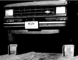
Vehicle properly mounted on ramps.
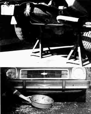
Vehicle properly mounted in jack stands; Placing o pan under
car.
THE GREASE JOB
Combine this job with the oil/filter change if possible.
Frequency: Every 6000 miles.
Tools and Supplies:
—Trouble light
—Car ramps or stand jacks
—Tarp or old blanket to lie on
—Grease gun
—Grease gun cartridge
—Rags
—Shop manual drawing showing location of grease fittings
Procedure: (Note—Follow all established safety procedures for jacking a car.)
1. Drive the front of the car onto car ramps or jack it up and place it on stand jacks. Use caution in either case. Block the rear wheels and set the parking brake on. (See Figs. 16-1 and 16-2.)
2. If the car has an automatic transmission place the shift in PARK. If the car has a manual transmission place the shift in REVERSE.
3. Load the grease gun with a cartridge of grease of the proper type (Fig. 4).
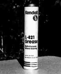
Fig. 4. Cartridge for grease gun.
4. Position the tarp or blanket underneath the front of the car. Locate and wipe clean all the grease fittings on the steering linkages and ball joints (Fig. 5).
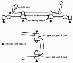
Fig. 5. Typical location of grease fittings.
5. Pump grease into each fitting until the boot at each location swells with grease. Note that some manufacturers install ball joints with plastic sleeves that do not require or allow greasing. Consult your shop manual to be sure. After the fitting has taken the required amount of grease, wipe it clean and go on to the next fitting.
6. Replace any fittings that do not take grease.
7. While the car is elevated, grease any transmission linkages that require periodic lubrication. Use the proper type of grease.
8. Remove the car from the ramps or stand jacks.
9. Move to the rear of the car. Remove the fill plug on the differential case and check for the proper amount of lubricant. Fill as required and replace the plug.
10. Properly dispose of grease rags and empty grease cartridges.
11. Record the date and mileage for the grease job.
AUTOMATIC TRANSMISSION SERVICE
Frequency: Every 25,000 miles, or every 10,000 miles if towing.
Tools and Supplies:
—Trouble light
—Car ramps or stand jacks
—Oil drain pan
—Funnel
—New automatic transmission fluid (amount and type specified in owner or shop manual)
—Rebuild kit for cleaning pan
—Wrenches to fit pan cover
—Clean, lint-free cloths or rags
—Tarp or old blanket to lie on
Procedure: (Note—follow all established safety procedures for jacking a car.)
1. Drive the car onto car ramps or jack it up and place it on stand jacks. Use caution in either case. Block the rear wheels and set the parking brake on. (See Figs. 16-1 and 16-2 above)
2. Place the shift in PARK.
3. Remove the transmission dipstick. Inspect the fluid on the stick for signs of trouble.
4. Place tarp or blanket under transmission.
5. Drain the transmission of all fluid into the oil drain pan. Refer to the instructions in the shop manual.
6. Remove transmission pan from bottom of transmission case (Fig. 6). Inspect the pan for sediment. Wipe clean with a lint-free cloth.
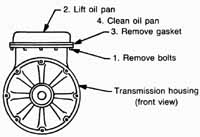
Fig. 6. Oil pan removal—clean dirt in bottom of pan.
7. Inspect the transmission fluid screen for dirt (Fig. 7). Clean, if necessary, in appropriate solvent.
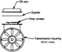
Fig. 7. Transmission filter screen.
8. After everything is clean, reinstall the screen and pan with the new parts in the rebuild kit according to the kit instructions (Fig. 16-8). Bolt the pan to the transmission housing according to the instructions in the shop manual.
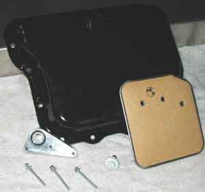
Fig. 8. Automatic transmission pan and filter kit
9. Refill the transmission with the proper amount and type of automatic transmission fluid. Do not overfill. Check for leaks around the pan. Reinstall the dipstick.
10. With the transmission at the factory recommended operating temperature, check the fluid level.
11. Remove the tarp or blanket.
12. Properly discard the old transmission fluid. Empty it into old milk jugs or into empty oil cans or bottles. Some gas stations will accept used transmission fluid for recycling.
13. Lower the car off the ramps or stand jacks.
14. Record the date and mileage for this service
CHANGING V-BELTS
Frequency: When inspection indicates a change is needed, or monthly.
Tools and Supplies:
—Fender cover
—Set of box wrenches or sockets with driver
—Crow bar or other pry bar
—Belt tension gauge
—New V-belt to suit application
—Rags
Procedure:
1. Inspect the belt for fraying, tearing, or glossing. If the belt exhibits any of these conditions it should be replaced (Figs. 16-9 and 16-10).
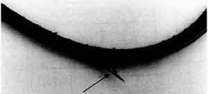
Fig. 9. Worn V-belt.
2. Loosen the tension bracket for the belt. The tension bracket is normally the one holding the alternator in place. Consult the shop manual for the proper bracket or brackets for your car.
3. With the bracket loosened the old belt should slip off easily. If it doesn’t readily come off the pulley, carefully use a pry bar to slip the belt. Be careful not to nick any of the pulley surfaces because nicks and scratches will quickly tear up the new belt.
4. Wipe the pulley with a clean, dry rag. Use cleaner if necessary.
5. Loop the new belt around the pulley, using the pry bar if necessary. Tighten the bracket until the belt flexes only about 1 inch. From this point on use the tension gauge to properly tension the belt. The shop manual will provide the proper settings of and location for the tensioner on the belt.
6. Run the engine at idle to check operation of the belt. It should not wobble or travel laterally on the pulley.
7. After a few days of operation on the road, check the belt tension again. Readjust if necessary.
8. Properly discard the worn V-belt.
9. Record the date and mileage the belt was changed.

Fig. 10. New V-belt.
CHANGING HOSES
Frequency: Every year or when inspection indicates a change is needed. Tools and Supplies:
—Drain pan
—Antifreeze mix
—Funnel
—Spade type or flat screwdriver
—Tube of gasket sealer (only if required by shop manual)
—Replacement hose
—Replacement hose clamps (screw type)
—Utility knife
—Emery cloth
—Cloths or rags
Procedure: (Note—this procedure applies to changing heater and radiator hoses.)
Heater Hoses
1. Inspect the heater hoses for leaks, bubbling of the hose wall and fraying. If the hose exhibits any of these conditions or is very old, replace it (Fig. 11).
2. Unsnap or unscrew the hose clamps located at both ends of the hose. Remove the hose.
3. Stuff a cork or rag in or tape the openings of the fittings that the hose fits onto to prevent excessive antifreeze leakage when the hose is removed. Otherwise, drain the cooling system.
4. Inspect the fittings. Lightly sand any corrosion deposits or bits of hose or dirt from the fittings with the emery cloth. Clean and wipe dry.
5. Cut a length of replacement hose of the proper size and type the same length as the old hose. Remove any tape or other obstruction used to plug the fittings or refill the cooling system.
6. If your shop manual advises using gasket sealer or cement, apply it to the fittings only—not the inside of the hose ends.
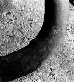
Fig. 11.Coolant hose with bubble.
7. Otherwise, slip hose clamps over the hose ends and then gently, but firmly, push the hose over the fittings the recommended amount. Twisting the hose slightly on the fitting as you push may help with getting the hose installed.
8. Replace the older design spring type hose clamps with screw type clamps (Figs. 16-12 and 16-13).
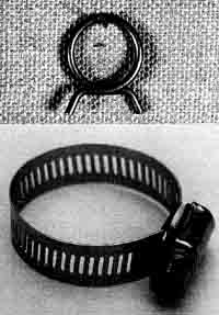
Fig. 12. Spring-type hose clamp. Fig. 13. Screw-type
hose clamp.
9. Tighten the hose clamps until firm, but not so tight that you begin cutting the hose with the clamp.
10. Refill the radiator or overflow tank making up for lost antifreeze.
11. Run the engine a few minutes checking for leaks.
12. Properly discard the old hoses.
13. Record the date and mileage of the hose replacement.
Radiator Hose
1. Inspect the radiator hoses for leaks and firmness of the hose wall. The hose should not feel soft or flimsy. If the hose is leaking or soft or is very old, replace it.
2. Drain the radiator, saving the fluid.
3. Unscrew the radiator hose clamps located at both ends of the radiator hose. Remove the old hose.
4. Inspect the fittings. Lightly sand any corrosion deposits or bits of hose or dirt from the fittings with the emery cloth. Clean and wipe dry.
5. If your shop manual advises using gasket sealer or cement, apply it to the fittings only—not the inside of the hose ends.
6. Otherwise, slip hose clamps over the hose ends and then push the hose over the fittings the recommended amount. If you encounter trouble getting the hose on the fittings, twist it back and forth slightly as you push until it is properly installed.
7. Tighten the hose clamps until firm, but not so tight that you begin cutting into the hose with the clamp.
8. Refill the radiator.
9. Run the engine a few minutes checking for leaks.
10. Properly discard the old radiator hose.
11. Record the date and mileage of the hose replacement.
CHANGING TIRES
Frequency: For rotation at 12,000 miles and to install snow tires.
Tools and Supplies:
—Proper jack for the car—see owner or shop manual
—Lug wrench
—Rags
—Penetrating oil
—Large flat screwdriver
Procedure:
1. Refer to the owner or shop manual for the proper position to place the jack. Follow the directions carefully. Avoid any shortcuts; safety first when using car jacks.
2. Before you raise the car remove the hub caps. Pry them off with the lug wrench or a large, fiat screwdriver.
3. Jack up the corner of the car you want to work on first. If you are using a bumper jack make sure it’s straight and firmly grounded so it can’t tip over.
4. Before the wheel leaves the ground as you are jacking it upwards, loosen the lug nuts but don’t remove them from the lugs just yet. Use penetrating oil if the nuts stick.
5. Continue raising the car just enough to gain the clearance between the tire and ground to remove the tire.
6. Remove the lug nuts, placing them inside the hub cap or some other secure place.
7. Slip the tire off the lugs.
8. Slip the replacement tire on the lugs, being careful not to scrape the lug threads.
9. Spin the lug nuts onto the lugs finger-tight.
10. Lower the car until the wheel just begins to make contact with the ground. Tighten the lug nuts. Tighten one nut then proceed across the hub to another nut. Continue this crisscross pattern of tightening until all the nuts are tightened.
11. Finish lowering the car and install the hub cap.
12. Proceed to the next wheel.
13. Store tires that are to be saved properly.
14. Record the date and mileage of the tire change.
SERVICING SHOCKS AND MUFFLERS
Frequency: Replace shocks every 25,000 miles, mufflers when they leak or are rusted through.
Tools and Supplies:
—Socket wrench set
—Pry bars, slittler, tailpipe cutter, and pipe expander
—Hammer
—Large flat screwdriver
—Penetrating oil
—Rags
—Heavy gloves
—New shock absorbers and/or bushings
—New muffler and hangers
—Exhaust system sealer
Procedure:
Shock Absorbers
1. Raise the car and support it as instructed in the service manual. This is very important: With a shock absorber removed the suspension could slip out of place in some models.
2. Soak both upper and lower shock mount bolts with penetrating oil and wait about
15 minutes. This will make the job much easier.
3. Remove the shock from the mount with he proper size ratchet wrench.
4. Inspect the shock for damage, leaks, and loss of resistance. Shocks cannot be repaired, so replace them—in pairs—if they exhibit any signs of trouble.
5. If the shock seems in good shape, inspect the rubber bushings. Perhaps the bushings are worn and are the real problem. Replace them and reinstall the shock. Otherwise, a new shock plus bushings are needed.
6. Tighten shocks only the recommended amount, as specified in the instructions that come with the shocks or as stated in the service manual.
7. Lower the car and road test.
8. Properly dispose of old shock absorbers.
9. Record the date and mileage of the shock absorber replacement.
Mufflers
1. Raise the car and support it as instructed in the service manual.
2. Inspect the muffler. Small holes caused by road debris may be repaired with a muffler repair kit available from auto stores.
3. Holes caused by rust-through or corrosion cannot normally be repaired very well and even if they can, the repair will not last long. It’s better to replace the muffler.
4. Stuff a rag into the end of the tailpipe with the engine running. If you hear any hissing sound the muffler is leaking and needs replacement (Fig. 14).
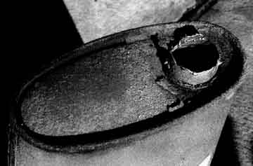
Fig. 14 Rusted muffler.
5. Carefully remove the muffler. If you plan to save the exhaust pipe, extension pipe, or tailpipe, be extra careful disconnecting the muffler from them. Sometimes removing a muffler is a tough job, so proceed slowly and deliberately. Wear heavy gloves to protect your hands from sharp metal edges.
6. Use the slittler and hammer to gradually peel away pipe ends for ease of removal. Consult the service manual for detailed instructions on removal.
7. Replace any broken or damaged hangers after the muffler is off (Fig. 16-15).
8. To salvage pipes, use a pipe expander to remove pipe clamp grooves and restore the pipe to its original size. Follow the directions that come with the tool.
9. Install the new muffler, coating the connections with exhaust system sealer or muffler cement.
10. Lower the car and road test. Make sure the muffler doesn’t wiggle or thump by road testing when the job is done.
11. Properly discard the used muffler.
12. Record the date and mileage of the muffler replacement.
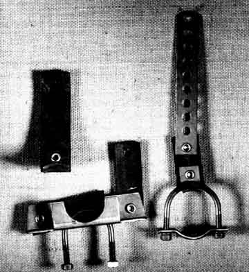
Fig. 15. Various pipe and muffler hangers.
DEGREASING THE ENGINE
Frequency: Twice a year or at tune-up time.
Tools and Supplies:
—Engine degreaser (Fig. 16)
—Aluminum foil or plastic wrap
—Rubber bands
—Duct tape
—Garden hose
—Old rags

Fig 16-16: Engine degreasers from Gunk and other brands.

Fig 16-17 Protect the carburetor with aluminum foil.
Procedure:
1. Remove the air cleaner assembly. Cover the top of the carburetor with foil or plastic wrap and secure with a rubber band or duct tape (Fig. 17).
2. Cover the distributor in the same manner.
3. Disconnect the battery cables and remove the battery. Cover the cable ends with foil or plastic.
4. Remove large chunks of grease with a rag. Wipe off excessive oil, also with a rag.
5. Follow the directions on the can of degreaser. Spray all areas to be cleaned with a thick foamy coating of degreaser. Wait the required amount of time.
6. Remove the foam and grease according to directions—usually this is done by spraying with a garden hose.
7. Finish by wiping difficult areas to remove residual grease. If necessary, reapply degreaser for a second treatment.
8. Uncover the carburetor, battery cables, and distributor. Reinstall the battery.
9. Record the date and mileage of the degreasing job.
SERVICING A CARBURETOR
Frequency: Twice a year.
Tools and Supplies:
—Tachometer
—Screwdrivers
—Socket wrench set
—Carburetor cleaner
—Pliers
—Thickness gauges
—Rags
—Carburetor adjustment specifications
Procedure:
1. Remove the air cleaner assembly.
2. Clean the entire exterior of the carburetor with carburetor cleaner.
3. Run the engine until it reaches operating temperature, then spray carburetor cleaner down the carburetor throat until all deposits are removed.
4. Adjust the idle speed to specification using the tachometer. Check the service manual for special instructions before proceeding.
5. While watching the tachometer gauge, turn the idle speed adjusting screw to bring the idle speed to specification. Turning the screw inward increases idle speed and outward decreases idle speed. See Fig. 18.
6. If the car has a throttle stop modulator, check it next. This modulator prevents continued running of the engine after the engine is turned off (dieseling). Locate the throttle stop modulator by referring to the service manual.
7. While an assistant shuts off the engine, check to make sure the modulator plunger retracts by closing the throttle. If there is a problem with the modulator you’ll have to buy a new one; it can’t be repaired.
8. Find the location of the idle mixture screws. With the engine running, turn the screws in slowly until the engine begins to run roughly. This means the mixture of air and fuel is lean—not enough fuel. Turn the screws out until the engine runs rough from too rich a mix, then turn the screws in again halfway between the lean and rich settings to obtain the best idle mixture setting.
9. Locate the automatic choke. Spray carburetor cleaner on all the moving parts of the choke. Wipe clean and oil the parts lightly with mineral oil. Make sure all the choke linkages move freely. There are many types of automatic chokes. Check with the service manual for additional service and adjustments for your particular car.
10. Check and adjust the anti-stall dashpot if the carburetor is equipped with an externally mounted one. Refer to the service manual. Check the clearance between the dashpot and the carburetor lever with a feeler gauge. If an adjustment is needed, loosen the lock nut and turn the dashpot until the proper clearance—as measured by the thickness gauge—is obtained. Retighten the locknut (Fig. 19).
11. Install the air cleaner assembly.
12. Record the date and mileage of the carburetor service.
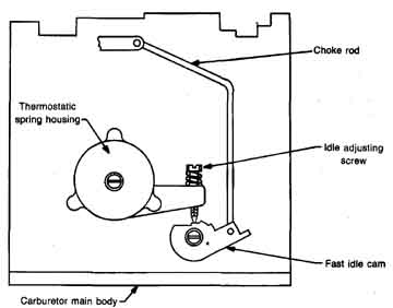
Fig. 18. Adjusting idle speed.
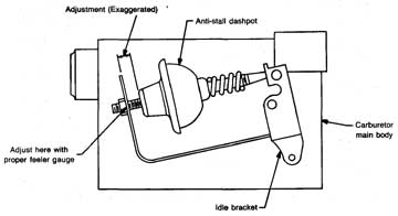
Fig. 19. Adjusting the dashpot.
SERVICING THE BATTERY
Frequency: Twice a year. Clean case once a year.
Tools and Supplies:
—Socket wrench set
—Distilled water
—Baking soda
— Battery syringe
—Hydrometer
— Battery post/terminal cleaning brush
—Petroleum jelly
—Terminal puller
—Small brush
Procedure: (Note—Follow the safety precautions in the service manila! when servicing the battery.)
1. Remove the battery cables from the battery using terminal pullers, if necessary.
2. Remove the battery hold-down clamps.
3. Lift the battery out of the car or leave it in place to work on it—whichever is easiest for you.
4. Scrub the top of the battery with a baking soda solution and a small brush. Be careful not to get any of the solution into the battery cells. Dry the battery (Fig. 20).
5. Clean the battery terminals and cable ends with the battery cleaning brush (Fig. 21).
6. Make sure the cables are not corroded or blistered. Replace them if required.
7. Install the cables onto the terminals. Coat them with petroleum jelly to avoid future corrosion.
8. Use the hydrometer to measure the specific gravity of the battery electrolyte. Tithe specific gravity of any cell is below 1.230, measured at 80 degrees Fahrenheit, the battery may have to be charged (Fig. 22).
9. Add any required distilled water to bring the electrolyte solution to the recommended full line with the battery syringe.
10. Refasten the battery hold-down clamps.
11. Record the date and mileage of the battery service.
(Note: The battery shown is a maintenance-free battery. If you remove the cell covers from this type of battery you may void the warranty. The covers must be resealed to avoid water loss. Therefore, perform this service only if you suspect a defective cell.)
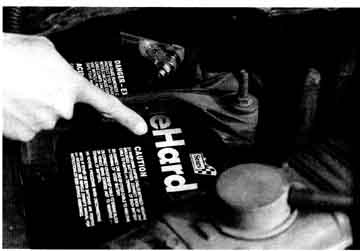
Fig. 20. Dirt collects here on battery case.

Fig. 21. Cleaning the battery terminals.
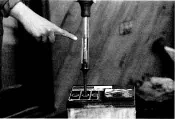
Fig. 22. Checking the battery charge with hydrometer.
CLEANING AND GAPPING THE SPARK PLUGS
Frequency: Twice a year or at every tune-up.
Tools and Supplies:
—Spark plug gauges and gap tool
—Ignition file
—Spark plug socket and wrench
—Rags
—Spark plugs
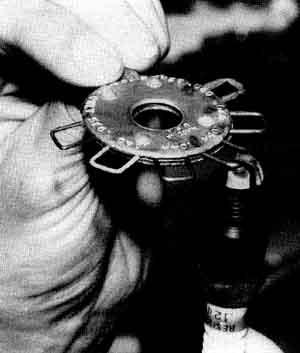
Fig. 23. Gapping the spark plug.
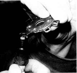
Fig. 24. Adjusting the electrode.
Procedure:
1. Remove the ignition cable from the spark plug, being careful not to pull the boot off the cable. Grab the boot, not the cable, when pulling.
2. Remove the plug with the proper size spark plug socket and wrench.
3. Inspect the plug for signs of engine trouble such as oil burning, oil fouling, and overheating of the plug. Take appropriate action.
4. Wipe or file deposits off the plug.
5. If the plug electrodes are worn too thin, replace the plug.
6. Gap the plug with the correct wire gauge using the gap tool to bend the side electrode (Figs. 16-23 and 16-24). Be careful not to bend the electrode too far or too many times; it could break off.
7. Install the spark plug into the engine. Be especially careful not to strip threads when installing the plugs.
8. Replace the ignition cable firmly over the spark plug.
9. Move on to the next plug and continue until all of them are done.
10. Properly discard any used plugs.
11. Record the date and mileage of the spark plug service.
SERVICING THE DISTRIBUTOR
Frequency: Twice a year or at every tune-up.
Tools and Supplies:
—Screwdriver
—Distributor cap
—Rotor
—Condenser (if equipped)
—Breaker points (if equipped)
—Ignition file
—Thickness gauges
—Needle-nose pliers
—Small wire brush
—Emery cloth (fine)
Procedure:
1. Remove the distributor cap and check for cracks. If cracked, replace it.
2. Remove the ignition wires from the distributor cap, being careful to note their correct terminal location. Mark them with tape and number them so you won’t get them mixed up.
3. Using a small wire brush clean the inside of each cap terminal. Wipe the cap clean of all oil, grease, and road dirt that can cause voltage leaks.
4. Very lightly sand the inside contacts of the cap and the center rotor contact button to remove carbon. If you sand too heavily you will ruin the cap. Do not remove any metal from the contacts (Fig. 25).
5. Attach the ignition cables to the distributor cap in the proper order and set the cap aside.
6. Remove the rotor and wipe clean with a dry cloth.
7. Inspect the rotor tip for chipping and burning. Scrape the tip clean if it’s not too badly burned, but don’t file it because that will increase the gap the spark must jump to the cap contacts. 11th doubt, install a new rotor. Make sure the spring contact on top of the rotor has enough tension to make proper contact with the center contact button inside the cap (Fig. 26).
8. If the distributor has breaker points, remove them and inspect the contacts for pitting and burning. File lightly or replace them.
9. Install the breaker points and properly gap them with the thickness gauge. Refer to the service manual for specifications and correct installation instructions.
10. Install the rotor and cap.
11. Properly discard used parts.
12. Record the date and mileage of the distributor service.
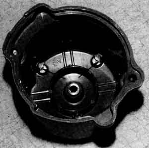
Fig. 25. Wear occurs at terminal points of the distributor cap.
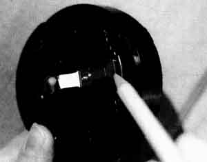
Fig. 26. Watch for wear of the rotor.
REPAIRING MINOR RUST
Frequency: Before minor rust turns into major rust-through.
Tools and Supplies:
—Power drill
—Wire brush for drill
—Degreaser
—Sandpaper
—Masking tape
—Primer paint
—Touch-up paint
—Wax
Procedure:
1. Inspect the car body for minor rust. Minor rust can be defined as surface rust that is less than one quarter of the thickness of the metal.
2. Look for minor rust around body trim moldings and all along the lower part of the body, especially at door bottoms.
3. Remove the rust with the brush and power drill until you get down to bright metal.
4. Lightly sand the surrounding edges of the paint, feathering them flush to the bright metal.
5. Clean the area with a degreaser such as carbon tetrachloride or some other commercially available product.
6. As soon as possible, apply primer to the bare metal according to the instructions on the bottle or can and let dry. Mask the area if need be to keep primer off good paint.
7. When sufficiently dry, apply touch-up paint over the primer. If more than one coat is necessary, sand lightly between coats for better adhesion.
8. Wax the area for protection.
FLUSHING THE COOLING SYSTEM
Frequency: Every 12,000 miles.
Tools and Supplies:
—Chemical flush solution
—T-connection
—Antifreeze
—Garden hose
Procedure:
1. Drain the cooling system. Use old milk jugs to dispose of the antifreeze.
2. Install a T-connection kit for flushing (Fig. 27). It is installed permanently.
3. Follow the instructions provided with the chemical flush and the T-connection kit for flushing.
4. Remove the cap from the T-connection and attach the garden hose.
5. Remove the radiator cap. Install the plastic deflector from the T-connection kit and tighten it in the radiator filter neck.
6. Turn on the garden hose. Water will flow out the plastic deflector. Make sure all the antifreeze is flushed out.
7. Add the chemical flush solution according to the directions on the can or bottle and reflush.
8. After flushing and disconnecting the garden hose, refill the cooling system with fresh antifreeze of the proper amount.
9. Run the engine with the radiator cap off for a few minutes to circulate fluid through the cooling system. Keep adding antifreeze until the system is full.
10. Install the radiator cap and clean up any spilled antifreeze.
11. Make sure the T-connection is properly closed off to prevent coolant leakage.
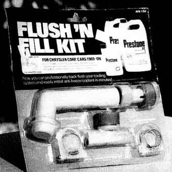
Fig. 27. Cooling system T-connection for flushing.
Prev: Putting
It All Together
Next:
A Short Course in Buying a Used Car
Home Automotive
Terms top
of page