Diesel fuel systems were entirely mechanical until the mid-1980s, when manufacturers of vehicle engines turned to computers to give more precise control over fuel delivery and timing. Mechanical systems continue to be specified for many agricultural, construction, and marine applications.
Air blast
Early engines used compressed air to force fuel into the cylinders against compression pressure. Injectors received fuel from a low-pressure pump and air from a common manifold, which was pressurized to between 800 and 1000 psi. The engine camshaft opened the injectors, appropriately enough called "valves," to admit a blast of compressed air and atomized fuel to the cylinders. A throttling valve regulated engine speed by controlling the amount of fuel delivered; air required no metering, since surplus air is always present in diesel cylinders.
Air injection had serious drawbacks. The air/fuel mixture could not penetrate deeply into cylinders that were themselves under 450-500 psi of compression pressure. Attempts to increase engine power by admitting more fuel merely dampened the flame. The compressors were parasitic loads that absorbed 15% and sometimes more of engine output. Nor did air injection make for a compact package: starting and four-stage air-injection compressors accounted for a third of the length 1914-era Krupp submarine engines.
Early common-rail
The need for more compact and silent submarine engines led the British arms maker Vickers to develop airless, or solid, injection. One can make the case that the ultimate consumers of nineteenth- and twentieth-century technology were enemy soldiers, sailors, and civilians. At any rate, solid injection was a vast improvement and, after the end of hostilities in 1919, was widely commercialized. Injectors fed from a common rail that was filled with high-pressure fuel and usually fitted with an accumulator to smooth pressure variations generated by injector opening and closing ( FIG. 1). Adjustable wedges between the camshaft lobes and the injector followers permitted injection duration to vary with speed and load.
Even so, this early form of c-r injection limited engine speed, since increasing the effective width of the wedge by forcing it deeper into contact with the cam also advanced the timing, causing the injector to open earlier. There were also maintenance concerns. According to contemporary accounts, the rails leaked and injectors dribbled fuel throughout the whole operating cycle.
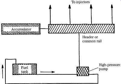
FIG. 1 The common, or third-rail system supplied fuel to cam-operated injectors
from a header, pressurized by a remote pump. By the late 1920s, c-r was being
phased out by Bosch inline pumps, only to be revived again as the century closed.
These new common-rail systems are discussed in the following section.
Jerk pump system
The big breakthrough came with the development of the Bosch inline pump, used today in a form almost identical to the first production run of April, 1927. The first pumps were mated with pintle injectors for indirect injection (IDI) applications.
Direct injection (DI) multiple-orifice injectors arrived in 1929 and, two years later, Bosch integrated centrifugal governors with the pumps. At this point, the modern diesel engine came into being.
The inline pump consists of a row of individual plungers, one per engine cylinder, operated by the same internal camshaft. High-pressure tubing connects each of the plungers to its injector. The spring-loaded injectors function like pop-off valves to open automatically when a certain pressure threshold is reached. The sudden loss of line pres sure gave rise to the term "jerk pump," which while a bit inelegant, is descriptive. The distributor pump was developed in the early 1960s as a means of reducing the number of extremely precise and expensive plungers. One pumping unit, consisting of one, two, or sometimes three plungers, serves all injectors. After pressurization, the fuel passes through a rotary valve, known as a distributor head, for allocation to the individual injectors. A distributor pump is the hydraulic equivalent of an ignition distributor. Because of their relatively low cost, distributor pumps are standard ware for automobiles and light trucks. The major disadvantage is that the internal cam, which drives the plunger set, depends solely upon fuel for lubrication.
Inline pumps lubricate the high-pressure cam faces with motor oil, either from an internal reservoir or from the engine oiling system.
FIG. 2 illustrates the layout of the jerk-pump system that, in this example, employs an inline pump. A distributor-type pump could be substituted.
A lift pump, shown on the lower left of the drawing, delivers fuel to the filters and from there to the suction side of the inline pump. High-pressure fuel exits the pump through dedicated lines to each injector. A second line made up to each injector recycles surplus fuel back to the tank. The system works at three pressure levels: low pressure, on the order of 30-50 psi, between the lift pump and injector pump, pressure of several thousand psi in the injector piping, and slightly more than zero pressure on the return line.
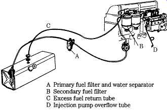
FIG. 2 An inline-pump system as used on Ford-based Lehman marine engines.
Inline pumps
The parts breakdown for a Bosch size A Series PE inline pump for six-cylinder engines is shown in FIG. 3. Shims (21 and 49) establish camshaft float. Two fuel delivery adjustments are provided. The basic setting is determined by the height of the adjustment bolts (35) that thread into the tops of each tappet. In addition, friction clamps (29) permit the control-sleeve pinions (30) to move relative to the rack to compensate for tooth wear and production tolerances. Fuel-delivery adjustments for this and all other injection pumps must be made on a test stand.
The drawing of a single-plunger pump in FIG. 4 helps to clarify the relation ship between the rack, fuel control gear (plunger pinion), and plunger. Fuel enters through the intake port on the right and exits past the delivery valve at the top of the unit. The obliquely cut groove on the plunger outer diameter (OD) functions in conjunction with the rack to throttle fuel delivery.
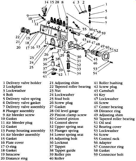
FIG. 3 Bosch Series PE pump. This example is found on six-cylinder Chrysler
marine engines.
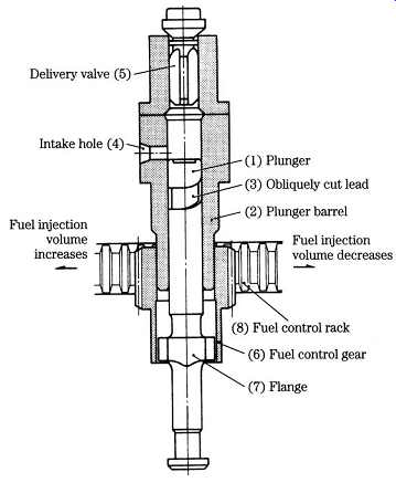
FIG. 4 Plunger, barrel, and rack assembly. The relief labeled "obliquely
cut lead" is generally called the "helix."
How this is done is shown in FIG. 5. At the bottom of the stroke, the plunger uncovers the inlet port. Fuel enters the pressure chamber above the plunger. The plunger rises, initially pushing fuel back out the inlet port. Further movement masks the inlet port. The plunger continues to rise, building pressure on fuel trapped above it. The delivery valve opens, and a few milliseconds later, the injector discharges. Fuel continues to flow until the annular groove milled along the side of the plunger uncovers the inlet port. At this point, pressure bleeds back through the inlet port and injection ceases. Because of the shape of the groove, rotating the plunger opens the inlet port to pressure earlier or later in the plunger stroke.
American Bosch, Robert Bosch, and CAV barrels are drilled with a second port above the inlet port to accept spillage during part-throttle operation. FIG. 6 illustrates the metering action of a CAV pump. Fuel enters the barrel at A and continues to flow until plunger movement masks the two ports (inlet shown on the left, spill port on the right). At full load, the pressure bleed-down through the spill port is delayed until the plunger approaches the end of its stroke, as shown in drawing C. You might wonder why the spill port opens before top dead center (tdc), when a few more degrees of cam movement would raise fuel pres sure even more. The reason is that cam-driven plungers behave like pistons, accelerating at mid-stroke and slowing as the dead centers are approached.
Opening the spill port early, while plunger velocity and pressure rise are rapid, terminates injection far more abruptly than if the port remained closed until the plunger reached tdc.
In drawing D, the annular groove has rotated to the half-load position. The effects of further rotation are shown at E, which represents idle, and at F, shutdown.
However the porting is arranged, the effective stroke has a constant beginning and a variable ending for pumps this guide is concerned with. Some marine and large stationary engines meter fuel delivery at the beginning of the stroke.
Details of the mechanism for transmitting rack movement to the plungers vary with the manufacturer, but always include an adjustment to equalize delivery between plunger assemblies. At a given rack position, each cylinder must receive the same amount of fuel.
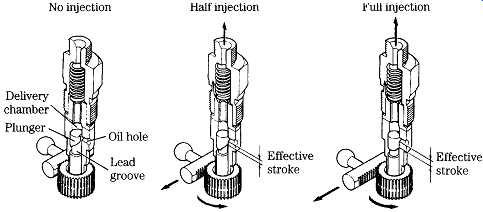
FIG. 5 Constant-beginning, variable-ending plunger action with surplus fuel
exiting through the inlet port.
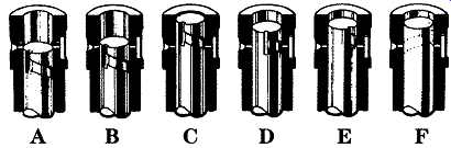
FIG. 6 A variation of the principle illustrated in FIG. 5, using a spill
port to vent the unneeded fuel. GM Bedford Diesel
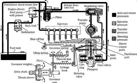
FIG. 7 Schematic of a Lucas-CAV distributor-pump system. GM Bedford Diesel
Distributor pumps
The main technical advantage of distributor pumps is that each cylinder receives precisely the same amount of fuel since all cylinders feed from the same plunger or plunger set. And, as pointed out above, reducing the number of plungers, which must be lapped to angstrom tolerances, reduces costs.
Lucas/CAV
FIG. 7 illustrates a CAV system for medium trucks. The engine-driven feed pump moves fuel from the tank to the filter and regulating valve. Fuel then passes to the transfer pump and, from there, to the inlet side of the distributor pump for pressurization and injection. As explained below, the regulating valve throttles the injection pump during low-speed operation. Surplus fuel returns to the tank through low-pressure lines.
A pair of cam-driven plungers, mounted on the pump rotor and turning with it, generate injector pressure ( FIG. 8). During the inlet stroke the plungers move out ward under pressure from fuel entering through the inlet (or metering) port. As the rotor continues to turn, the inlet port is blanked off by the rotor body and one of the outlet ports is uncovered.
As the outlet port is uncovered, the internal cam, acting through rollers, forces the plungers together. Fuel passes through the port for injection. Fuel that slips by the plungers returns to the filter.
The amount of fuel delivered per plunger stroke is determined by the regulating valve (upper right in FIG. 7) that is controlled by the accelerator pedal and the centrifugal governor. At low engine speeds, the regulating valve limits the pressure of fuel going to the transfer pump and into the injection pump. Because the pump plungers are driven apart by incoming fuel, their outward displacement is determined by transfer-pump pressure. As engine speed and/or load increase, the regulating valve increases fuel pressure to force the pump plungers further apart. Unlike Bosch inline pumps, which throttle by varying the effective stroke, the Lucas/CAV unit varies the actual stroke.
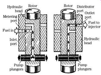
FIG. 8 Opposed-piston distributor pump operation. GM Bedford Diesel
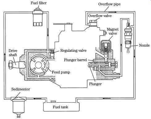
FIG. 9 Typical small-engine distributor-type system. Yanmar Diesel
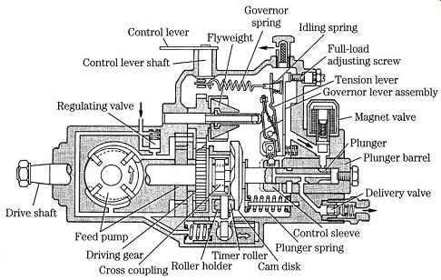
FIG. 10 Bosch VE Series injection pump.
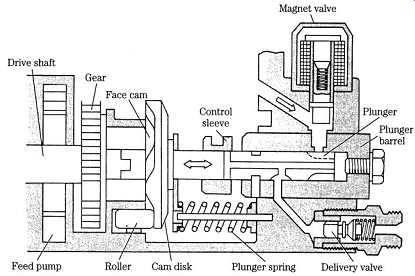
FIG. 11 Cross-sectional view of the VE. Notice the integration and compactness
of the design.
FIG. 12 The VE plunger reciprocates in the pumping function and rotates in
the distributor, or fuel-allocation, function. Yanmar Diesel
Bosch VE
Nearly 50 million VE pumps have been produced since introduction in 1975 with applications ranging from fishing boats to luxury automobiles. FIG. 9 sketches a basic installation, with filter, gravity-type water separator (sedimentor), fuel lines from the pump and injectors, and a solenoid-operated fuel shutoff (magnet) valve. Normally the fuel shutoff requires battery power to open; for marine applications the valve must be energized to close. This permits the engine to continue to run should the vessel lose electrical power.
The VE turns at half engine speed and is geared to a mechanical (shown in FIG. 10) or electronic governor. The rear half of the pump houses the vane-type transfer pump and regulator that supplies the high-pressure section with fuel at pressures ranging from 40 psi to 175 psi at full throttle. Vane-pump pressure also controls the hydraulic timer that advances injection with increased engine speeds.
A tongue-and-groove joint mates the rear half of the two-piece drive shaft with the forward, or plunger, half. This joint, which can be seen clearly in FIG. 11, permits the forward half of the shaft to move fore and aft as it rotates under the impetus of the face cam. The cam reacts against the housing through roller bearings, oriented as shown in FIG. 12.
A control sleeve regulates the effective stroke of the plunger, which discharges through delivery valves on the distributor head.
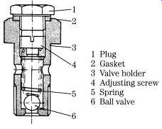
FIG. 13 Fuel overflow valve functions as an automatic bleeder, diverting
air and surplus fuel back to tank. Marine Engine Div., Chrysler Corp.
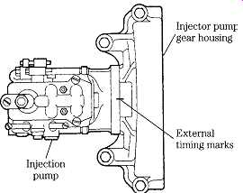
FIG. 14 Timing marks on a Bosch distributor pump. Ford Motor Co.
Injector pump service
Bleeding:
Because surplus fuel recycles to the tank or filter through fuel overflow valves mounted at high points on pumps and injectors, a half-hour or so of operation is generally sufficient to purge the system of air bubbles ( FIG. 13). More serious air intrusions require bleeding, using procedures described in Section 4 for conventional, pre-computer engines and elaborated upon in Section 6 for more modern engines.
Timing:
Injection pumps have two provisions for synchronizing fuel delivery with piston movement. Timing marks on the drive gears establish the basic relationship.
Elongated mounting-bolt holes, which allow the pump body to be rotated a few degrees, provide the fine adjustment. Reference marks stamped on the pump body and mounting flange enable the adjustment to be replicated ( FIG. 14).
Before removing a pump, bar the engine over until both valves on No. 1 cylinder close and the timing mark on the harmonic balancer or flywheel aligns with its pointer.
This procedure indexes pump-gear timing marks for easy assembly. If the same pump is reinstalled, the reference marks on the pump body and flange should be valid.
Substituting another pump puts the marks into question and the engine should be retimed, either statically or dynamically.
Static timing procedures vary enormously, but the purpose of the exercise is to synchronize the onset of fuel delivery with the piston in No. 1 cylinder. Depending upon engine make, model, and application, fuel should begin to flow anywhere from 8-22_ btdc as the flywheel is barred over by hand.
Flywheels for small utility engines generally have two marks inscribed on their rims: one representing tdc and the other, always in advance of the first, indicating when fuel should begin to flow from No. 1 delivery valve. A convenient way to monitor fuel flow is to make up an adapter out of a length of clear plastic tubing and a delivery-valve fitting, as shown in FIG. 15. The mechanic slowly bars the engine over, while watching for the slightest rise in the fuel level. The onset of fuel movement should occur at the moment the timing mark aligns with its pointer. If tdc is passed and the plunger retreats, the flywheel must be turned back 15_ or so to absorb gear lash, and the operation repeated.
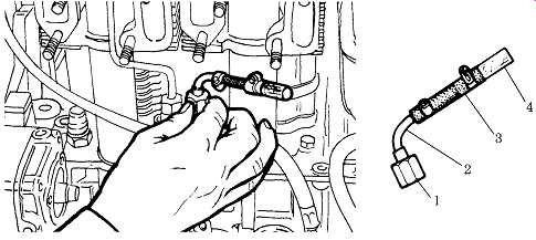
FIG. 15 Transparent section (4) of fuel pipe adapter indicates plunger movement
for timing purposes. Lombardini
Drive gears for Navistar (International) DT358 and its cousins have six timing marks. Which one to use depends upon the engine model and application. In a reversal of traditional practice, certain American Bosch pumps time to the end, rather than the onset, of fuel delivery. The delivery valve, which acts as a check valve, for No. 1 plunger must be disabled before timing.
Timing specifications for distributor pumps are often expressed in thousandths of an inch of plunger movement from bdc. FIG. 16 illustrates the dial-indicator adapter that replaces the central bolt in the distributor head. Locating bdc-the precise moment when the plunger pauses at the bottom of its stroke-requires patience.
Once bdc is found, the mechanic zeros the gauge and bars the engine over in the normal direction of rotation to the appropriate crankshaft or harmonic-balancer mark. He then rotates the pump body as necessary to match lift with the published specification.
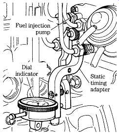
FIG. 16 For critical applications, plunger travel is measured with a dial
indicator. Ford Motor Co.
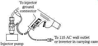
FIG. 17 Sun-timing light triggers from pulses in the fuel pipe.
Dynamic timing, made with a strobe light while the engine ticks over at slow idle, compensates for pump-gear wear and other variables. It’s the only way that van and other inaccessible engines can be timed.
The Sun timing light draws power from a wall outlet or, if equipped with an inverter, from the engine's 12-V or 24-V batteries ( FIG. 17). A transducer clamps over No. 1 fuel line to trigger the strobe when the injector opens and the sudden drop in fuel pressure contracts the line. The instrument also tracks how many crank shaft degrees the timing advances as engine speed increases.
Unit injectors (UIs), which integrate the pump function with injection, are timed as described below.
Repair
Other than periodically checking the oil level for in-line pump reservoirs and adding rust inhibitor to the fuel before long-term storage, injector pumps require no special attention. When loss of pressure indicates that the pump has failed, the mechanic farms the unit out to a specialist for cleaning or repair.
While most mechanics would tackle Bosch VE, inline pumps are simple devices that can be opened for cleaning and elementary repairs. But the work requires patience and the highest possible levels of cleanliness. Plungers are lapped to their barrels and must be assembled as found. Nor should these sensitive parts be touched with bare fingers. Wear surgical gloves or use forceps. Tappets and other adjustable parts must be kept with their plungers. When disassembly entails loss of adjustment, the existing adjustments must be scribe marked. If at all possible, obtain a drawing of the pump before you begin.
Inline pumps come apart as follows:
• Unscrew the delivery valves mounted above each barrel and lay them out in sequence on the bench, which should be covered with newspaper to reduce the possibility of contamination.
• Most inline pumps incorporate a side cover for tappet access; others mount the individual plunger assemblies from above with studs. On those with side covers, rotate the camshaft to bring each tappet to the top of its stroke and shim the tappet. Withdraw the plungers from the top with the aid of a hooked wire or expansion forceps. Mark or otherwise identify the plungers for correct assembly.
• Inspect the lapped surfaces with a magnifying glass. Deep scores or pronounced wear marks mean that the pump has come to the end of its useful life.
Over-tightening the delivery valves warps the barrels and produces uneven wear patterns. Water or algae in the fuel leave a dull, satiny finish on the rubbing surfaces. Loss of the sharp edges on the helix profile upsets calibration.
• A plunger should fall of its own weight when the barrel is held 45_ from vertical. Gummed or varnished plungers can make governor action erratic and accelerate wear on the helixes and rack.
• If you have the specifications, check the cam profile with an accurate (i.e., recently recalibrated) micrometer.
• Examine the rack teeth for wear. FIG. 18 illustrates, in exaggerated fashion, the wear pattern. The rack should move on its bushings with almost no perceptible side or vertical play. Installation of new bushings requires a factory reamer.
Delivery valves
Injectors feed through delivery valves mounted on the distributor head or above each barrel on inline pumps. These check valves open under pressure to supply fuel to the injectors and close automatically during the suction stroke. Most delivery valves consist of a conical sealing element shaped like an inverted top hat ( FIG. 19).
The extension below the element, known as the piston, has two functions. It centers the valve over its seat and acts as a ram to force fuel back into the pump as the valve closes. This action assures a rapid drop in pressure so that the injector snaps shut without after-dribble.
Delivery valves come in various shapes and sizes. Some replace the conical element with a disc, others hold a certain percentage of pressure in the downstream plumbing after closing. But all work on the same general principle.
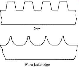
FIG. 18 Control-rack teeth bell-mouth in service. GM Bedford Diesel
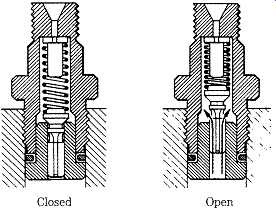
FIG. 19 Fuel delivery valve operation. GM Bedford Diesel
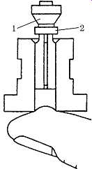
FIG. 20 Delivery valve test. Check valve shown at 1, piston at 2. Marine Engine
Div, Chrysler Corp
Service
Delivery-valve problems are cylinder specific. If the valve sticks open, no fuel passes to the associated injector. Leakage is harder to diagnose. White smoke that persists after all bases have been touched-pump pressure and timing, new injectors, and engine compression-suggests that one or more delivery valves may be at fault.
Disassemble one valve at a time, clean the parts thoroughly, and test for leaks by blowing through the outlet port. Older, simpler valves can sometimes be resurfaced.
Check piston fit by depressing the valve and placing your finger over the inlet port ( FIG. 20). You should feel the vacuum as the piston falls.
Prev. | Next
Home top
of page Similar articles