Cleaning
Ford Motor and other manufacturers say that dirt is the chief cause of callbacks after major work. The direct effect is to contaminate the oil supply; the indirect effect is to create an environment that makes craftsmanship difficult or impossible.
The need for almost septic standards of cleanliness argues against the practice of opening the engine for less than comprehensive repairs. Of course, it happens that such repairs must be made, regardless of the long-term consequences. Nor is it possible to maintain reasonable standards of cleanliness during in-frame overhauls, although the damage can be minimized by moving in quickly, cleaning only those friction surfaces that are opened for inspection, and getting out. Dirt accumulations on internal parts of the engine cannot be removed from below, while parts are still assembled, and attempts to do so will only release more solids into the oil stream.
When, on the other hand, the engine is rebuilt, the block, cylinder head, pan, and other steel stampings are sent out for thermal or chemical cleaning (see Section 7). These processes also remove the paint, which is all to the good. Crankshaft, piston assemblies, and other major internal parts receive a preliminary wash-down for inspection by the mechanic in charge of the job. These parts are then forwarded to the machine shop for evaluation. When pistons are reused, the machinist will chemically clean the grooves and piston undersides-chores that save hours of labor. About all that remains for the shop mechanic is to degrease fasteners and accessories that have been detached from the block and remove the rust preventative from new parts.
Teardown
Drain the oil and coolant and degrease the outer surfaces of the engine.
Disconnect the battery, wiring harness (make a sketch of the connections if the harness is not keyed for proper assembly), and exhaust system. Attach the sling and undo the drive line connection and the motor mounts. With the engine secured in a stand, detach the manifolds, cylinder heads, and oil sump. The block should be stripped if you contemplate machine work or chemical cleaning of the jackets.
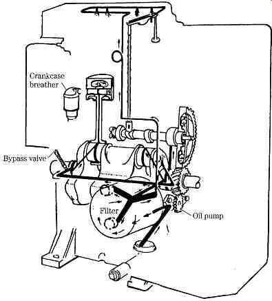
FIG. 13 Lubrication system.
Lubrication system
The first order of business should be the lubrication system. To check it out you must have a reasonably good notion of the oiling circuits. FIG. 13 is a drawing of the Onan DJ series lubrication system. The crankcase breather is included because it has much to do with oil control. Should it clog, the engine will leak at every pore. Oil passes from the screened pickup tube (suspended in the pan) to the pump, which sends it through the filter. From there the filtered oil is distributed to the camshaft, the main bearings (and through rifle-drilled holes in the crankshaft to the rod bearings and wrist pin), and to the valve gear. Valve and rocker arm lubrication is done through a typically Onan "showerhead" tube.
Tiny holes are drilled in the line and deliver an oil spray at about 25 psi. On its return to the sump, the oil dribbles down the push rods to lubricate the cam lobes and tappets.
The system in FIG. 14 is employed in six-cylinder engines. From the bottom of the drawing, oil enters the pickup tube, then goes to the Gerotor pump. Unlike most oil pumps, this one is mounted on the end of the crankshaft and turns at engine speed. The front engine cover incorporates inlet and pump discharge ports. Oil is sent through a remote cooler (6), then directed back to the block, where it exits again to the filter bank (11). Normally oil passes through these filters. However, if the filters clog or if the oil is thick from cold, a pressure differential type of bypass valve (12) opens and allows unfiltered flow.
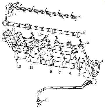
FIG. 14 A more complex lubrication system. International Harvester.
The main oil gallery (3) distributes the flow throughout the engine. Some goes to the main bearings and through the drilled crankshaft to the rods. The camshaft bearings receive oil from the same passages that feed the mains. The rearmost cam journal is grooved. Oil passes along this groove and up to the rocker arms through the hollow rocker shaft. On its return this oil lubricates the valve stems, pushrod ball sockets, tappets, and cam lobes. Other makes employ similar circuits, often with a geared pump.
FIG. 15 describes the Ford 2.3L lubrication system, which is surprisingly sophisticated for a small and, by diesel standards, inexpensive product. Pressurized oil goes first to the filter, described in the following section.
Depending on oil temperature, output from the filter goes either directly to the main distribution gallery or to the gallery by way of an oil cooler ( FIG. 16). A thermostatic valve, located in the filter housing, directs the flow ( FIG. 17). Cooling the oil during cold starts is counterproductive, and the valve remains closed; as oil temperature increases, the valve extends to split the flow between the gallery and cooler.
At approximately 94°C, all flow is diverted to the cooler. As a safety measure, the bypass valve opens if cooler pressure drop exceeds 14 psi. Thus, a stoppage won’t shut down oil flow, although long-term survivability is compromised.
Camshaft lubrication, a weak point on many ohc engines, shows evidence of careful attention. A large-diameter riser, feeding from the main gallery, supplies oil to the center camshaft bearing. At that point the flow splits, part of it entering the hollow camshaft and part of it going to an overhead spray bar. The camshaft acts as an oil gallery for the remaining two shaft bearings; the spray bar provides lubrication for camshaft lobes, rockers, and valve tips.
The main bearings are lubricated through rifle-drilled ports connecting the webs and main gallery. As a common practice, diagonal ports drilled in the crankshaft convey oil from the webs to adjacent crankpins. Spray jets, again fed by the main gallery, cool the undersides of the pistons and provide oil for the piston pins. A gear and crescent pump-the lightest, most compact type available-supplies the necessary pressure.
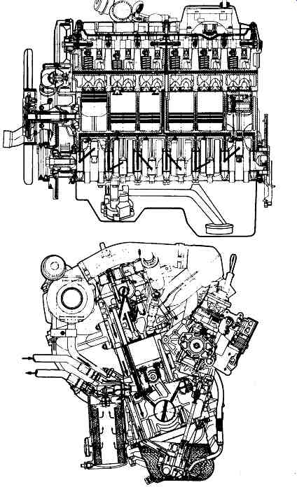
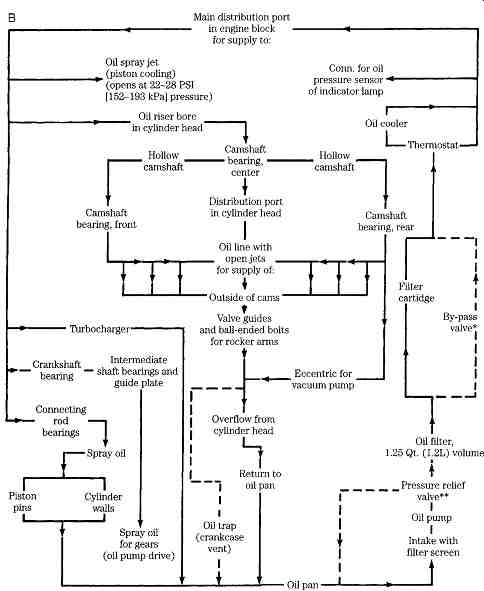
FIG. 15 Ford 2.4L lubrication system.
This cursory examination of the oil circuitry on three very different engines should underscore the need to come to terms with these systems. No other system has such immediate implications for the integrity of the mechanic's work.
Clogging is the most frequent complaint, caused by failure to change oil and filters at proscribed intervals, and abetted by design flaws. Expect to find total or partial blockage wherever the oil flow abruptly changes direction or loses velocity.
Prime candidates are the cylinder head/block interface, spray jets, and the junctions between cross-drilled passages. Neither immersion-type chemicals, heat, nor com pressed air can be depended on to remove metal chips and sludge. Drilled passages must be cleared by hand, using rifle-bore brushes and solvent.
Thorough cleaning is never more important than after catastrophic failure, which releases a flood of metallic debris into the oiling system. In this case, the oil cooler can present a special problem. Modern, high-density coolers don’t respond well to chemical cleaners and frustrate even the most flexible swabs. A new or used part- whose history is known-is sometimes the only solution.
Leaks can develop at the welch (expansion) plugs or, less often, at the pipe plugs that blank off cross-drilled holes and core cavities. It’s also possible for cracks to open around lifter bores and other thin-section areas. A careful mechanic will discard welch plugs (after determining that spares are available!) and apply fresh sealant to pipe plug threads during a rebuild. Most oil-wetted cracks can be detected visually.
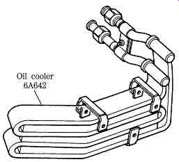
FIG. 16 Oil cooler.
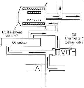
FIG. 17 Thermostatic bypass valve.
Internal leaks that have been missed will show when the system is filled with pressurized oil before start-up.
Filters
All contemporary engines employ full-flow filtration, using single or tandem paper-element filters in series with the pump outlet. Pleated paper filters can trap particles as small as 1 _m but are handicapped by limited holding capacity.
Consequently, such filters incorporate a bypass valve that opens to shunt the element when the pressure drop reaches about 15 psi ( FIG. 18), an action that should trigger a warning lamp on the instrument panel ( FIG. 19). Otherwise the operator should occasionally feel the filter canister to verify that warm oil is circulating.
The Ford 2.3L filter consists of two concentric elements, one in series with the oiling circuit, the other in parallel ( FIG. 20). As long as the bypass valve, shown at the top of the drawing, remains seated, pump output passes through the outer, series-connected element and into the lubrication circuit. Pump delivery rates are greater than the system requires and the surplus migrates through the inner filter and returns to the sump through the 9-mm orifice at the base of the assembly. I have been unable to obtain precise data for this engine, which was designed in Japan. However, standard design practice is to calculate diesel lube oil requirements as 0.003 times the ratio of oil to piston displacement times rpm. Pumps are then sized to meet twice these requirements. If this holds, the parallel filter makes a major contribution.
The most important single maintenance activity is to change the oil and filter on the engine-maker's schedule, which is more demanding than suggested for equivalent spark ignition (SI) engines. A turbocharger increases bearing loads and blowby, further shortening oil and filter life.
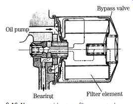
FIG. 18 Yanmar cartridge-type filter mounts down stream of the pressure-regulating
valve and includes a bypass valve.
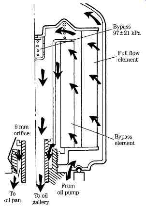
FIG. 20 Ford series/parallel filter.
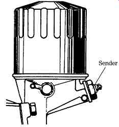
FIG. 19 Peugeot automotive diesels alerted the driver when the filter clogged.
The final steps in an overhaul or rebuild are to prime the oil pump by rotating the shaft with the impeller submerged in a container of clean motor oil, fill the turbocharger cavity and feed line, and pressurize the oiling circuit. The latter is accomplished by connecting a source of oil pressure to the main distribution cavity, usually by way of the oil-pressure sender tap. This step is sometimes omitted and the bearings-even though pre-oiled during assembly-suffer for it. The system must be pressurized after a new camshaft is installed.
Any repairs involving the turbocharger should be followed by disconnecting the oil return line and cranking until flow is established.
Before start-up after routine oil and filter changes, it’s good practice to dry crank the engine until the panel gauge indicates that oil pressure has been restored.
Lube oil
Oil collects moisture from condensation in the sump and is the repository for the liquid by-products of combustion. These by-products include several acid families that, even in dilute form, attack bearings and friction surfaces. No commercially practical filter can take out these contaminants. In addition oil, in a sense, wears out. The petroleum base does not change, but the additives become exhausted and no longer suppress foam, retard rust, and keep particles suspended. Heavy sludge in the filter is a sure indication that the change interval should be shortened, because the detergents in the oil have been exhausted. In heavy concentrations water emulsifies to produce a white, mayonnaise-like gel that has almost no lubrication qualities.
Oil that has overheated oxidizes and turns black. (This change should not be confused with the normal discoloration of detergent oil.) If fresh oil is added, a reaction might be set up that causes the formation of hard granular particles in the sump, known as "coffee grounds." Oil change intervals are a matter of specification-usually at every 100 hours- and sooner if the oil shows evidence of deterioration. Most manufacturers are quite specific about the type and brand to be used. Multigrade oils (e.g., 10-30W) are not recommended for some engines, because it’s believed they don’t offer the protection of single-weight types. Other manufacturers specify SF grades. As a practical matter this specification means that multigrade oils can be used. Brand names are important in diesel service. Compliance with the standards jointly developed by the American Petroleum Institute, the Society of Automotive Engineers, and the American Society for Testing and Materials is voluntary. You have no guarantee that brand X is the equivalent of brand Y, even though the oil might be labeled as meeting the same API-SAE-ASTM standards. General Motors suggests that you discuss your lubrication needs with your supplier and use an oil that has been successful in diesel engines and meets the pertinent military standards. MIL-L-2104B is the standard most often quoted, although some oils have been "doped" with additives to meet the API standards. These additives cause problems with some engines often in the form of deposits around the ring belt. For GM two-cycles zinc should be held in between 0.07% and 0.10% by weight, and sulfated ash to 1.0%.
If the lubricant contains only barium detergent-dispersants, the sulfated-ash con tent can be increased by 0.05%. High-sulfur fuels might call for low-ash series 3 oils, which don’t necessarily meet military low-temperature performance standards. Such oils might not function as well as MIL-L-2104B lubricants in winter operation.
Oil pumps
The Gerotor pump shown in FIG. 21 is gear-driven; a more common practice is to drive pumps of this type directly from the crankshaft. Like the Wankel engine, which employs a similar trochoidal geometry, operation is somewhat difficult to visualize on paper and obvious in the hardware. The inner rotor, which has one lobe less than the outer rotor, "walks" as it turns, imparting motion to the outer rotor and simultaneously varying the volume of the working cavity (shaded in the drawing).
Volume change translates as a pressure head.
The clearance between the rotors and the end cover is best checked with Plasti-Gage. Plasti-Gage consists of rectangular-section plastic wire in various thicknesses. A length of the wire is inserted between the rotors and cover. The working clearance is a function of how much the wire is compressed under assembly torque. The package has a scale printed on it to convert this width to thousandths of an inch. Plasti-Gage is extremely accurate and fast. The only precautions in its use are that the parts must be dry, with no oil or solvent adhering to them, and that the wire must be removed after measurement. Otherwise it might break free and circulate with the oil, where it can lodge in a port. Typical end clearance for a Gerotor pump is on the order of 0.003 in. Of course, all rubbing surfaces should be inspected for deep scratches, and the screen should be soaked in solvent to open the pores.
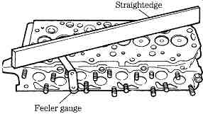
FIG. 21 Gerotor pump. Yanmar Diesel Engine Co. Ltd.
FIG. 22 Use a feeler gauge to determine outer rotor to case clearance (A)
and inner to outer rotor clearance.
Wear limits for the Yanmar and most other such pumps are 0.15 in. (B).

FIG. 23 Exploded view of typical gear-type oil pump. Marine Engine Div.,
Chrysler Corp.
Other critical specifications are the clearance between the outer rotor and the case ( FIG. 22A) and the approach distance between inner and outer rotors (B).
Camshaft-driven gear-type pumps are the norm ( FIG. 23). Check the pump for obvious damage-scores, chipped teeth, noisy operation. Then measure the clearance; the closer the better as long as the parts are not in physical contact.
End clearance can be checked by bolting the cover plate up with Plasti-Gage between the cover and gears, or with the aid of a machinist's straightedge. Lay the straightedge on the gear case and measure the clearance between the top of the gear and the case with a feeler gage. When in doubt, replace or resurface the cover. Check the diameter of all shafts and replace as needed. The idler gear shaft is typically pressed into the pump body. Use an arbor press to install, and make certain that the shaft is precisely centered in its boss. Allowing the shaft to cant will cause interference and early failure. Total wear between the drive shaft and bushing can be determined with a dial indicator as shown in FIG. 24. Move the shaft up and down as you turn it. Check the backlash with a piece of solder or Plasti-Gage between the gears. For most pumps this clearance should not exceed0.018 in.
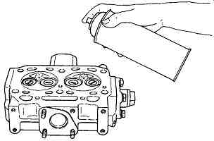
FIG. 24 Determining shaft-bearing wear. Marine Engine Div., Chrysler Corp.
In general, it’s wise not to tamper with the pressure relief valve, which might be integral with the pump or at some distance from it. If you must open the valve, because of either excessive lube oil pressure or low pressure, observe that the parts are generally under spring tension and can "explode" with considerable force. Check the spring tension and free length against specs, and replace or lap the valve parts as needed. When this assembly has been disturbed it’s imperative that the oil pressure be checked, with an accurate instrument such as the gauge shown in FIG. 25.
FIG. 25 Oil pressure check. Peugeot
Oil pressure monitoring devices
Because oil pressure is critical, it makes good sense to invest in some sort of alarm to supplement the usual gauge. Gauge failure is rare (erratic operation of mechanical gauges is usually caused by a slug of hardened oil impacted at the gauge fitting), but it does happen. Failure to shut down when pressure is lost will destroy the engine in seconds.
Stewart-Warner monitor Stewart-Warner makes an audiovisual monitor that lights and buzzes when oil pressure and coolant temperatures exceed safe norms. The indicator is a cold-cathode electron tube, which is much more reliable than the usual incandescent bulb. Designed for panel mounting, the 366 T3 is relatively inexpensive insurance.
Onan monitor Onan engines can be supplied with an automatic shutdown feature. The system employs a normally on sensor element and a time delay relay. In conjunction with a 10 W, 1-ohm resistor, this relay allows the engine to be started. When running pressure drops below 13 psi, the sensor opens, causing the fuel rack to pull out.
The sensor ( FIG. 26) is the most complicated part of the system. It has a set of points that should be inspected periodically, cleaned, and gapped to 0.040 in.
When necessary, disassemble the unit to check for wear in the spacer, fiber plunger, and spring-loaded shaft plunger. The spacer must be at least 0.35 in.
long. Replace as needed. Check the action of the centrifugal mechanism by moving the weights in their orbits. Binding or other evidence of wear dictates that the weights and cam assembly be replaced. The cam must not be loose on the gear shaft.
Ulanet monitor The George Ulanet Company makes one of the most complete monitoring systems on the market ( FIG. 27). It incorporates an optional water level sensor, overheat sensor, fuel-pressure sensor, and low- and high speed oil sensors. For the GM 3-71 and 4-71 series, these sensors are calibrated at 4 psi and 30 psi, respectively.
FIG. 26 Onan oil pressure monitor-sensor section.
FIG. 27 Ulanet monitor as con figured for DD two-cycle engines.
Crankcase ventilation
The crankcase must he vented to reduce the concentration of acids and water in the oil. A few cases are at atmospheric pressure; others (employing forced-air scavenging) are at slightly higher than atmospheric; and still other systems run the crankcase at a slight vacuum to reduce the possibility of air leaks. The vapors might be vented to the atmosphere or recycled through the intake ports. In any event, the system requires attention to ensure that it operates properly. A clogged mesh element or pipe will cause unhealthy increases in crankcase pressures, forcing oil out around the gaskets and possibly past the seals, as well as increasing oil consumption. Figure 28 shows a breather assembly with check valve to ensure that the case remains at less than atmospheric pressure.

FIG. 28 Yanmar atmospheric crankcase breather.
Prev. | Next
Home top
of page Similar articles