There comes a time when work stops and the mechanic becomes abstracted, distant from the task at hand. Something about the machine does not conform to the picture in the mechanic's mind. Images flash by until he or she finds one that most closely conforms to actual conditions. Once that is done, repairs can begin.
Constructing visual images is what mechanics do; the other stuff is mere wrench-twisting.
This section provides grist for these mental images. Because the material must be conveyed in words, it tends to be abstract. But once you can picture how these engines work, you will have made the first step in the journey to becoming a real mechanic.
Spark-ignition engines operate in a cycle consisting of four events: intake, compression, expansion (or power), and exhaust. A fresh charge of air and fuel is inducted into the cylinder, which then is compressed by the piston and ignited by the spark plug. The pressure created by combustion reacts against the piston to generate torque on the crankshaft. The spent gases then exhaust into the atmosphere.
Four-stroke-cycle engines require four up and down strokes of the piston, or two full crankshaft revolutions, to complete the cycle. Two-stroke-cycle engines telescope events into two strokes or one crankshaft revolution. For convenience we abbreviate the terms to four-cycle or four-stroke, and two-cycle or two-stroke.
Two-cycle operation
Focus on the piston. The double-acting piston works in both directions to compress the air-fuel mixture in the cylinder above it and in the crankcase below it. The piston and connecting rod convert a portion of the heat and energy released by combustion into mechanical motion that turns the crank shaft. Were that not enough, the piston also acts as a slide valve to open and close exhaust, transfer and (in some applications) intake ports. Because it works so hard, the piston is the first mechanical part to fail on two-cycle engines.
Third-port engines
Third- or piston-ported engines have three ports cast or milled into their cylinder liners. The inlet port admits fuel to the crankcase, the transfer port conveys fuel from the crankcase into the combustion chamber, and the exhaust port opens to the atmosphere.
First, let's look at events above the piston during a full turn of the crank shaft. In FIG. 1A the piston approaches the upper limit of travel, or top dead center (TDC), and has compressed the air-fuel mixture above it. The piston has also uncovered the inlet port to admit fuel and air from the carburetor to the crankcase. Figure 1-1B illustrates the beginning of the power stroke under the impetus of expanding combustion gases. As the piston falls, it first uncovers the exhaust port (FIG. 1C) and, a few degrees of crankshaft rotation later, the transfer port (Fig.1-1D). Fuel and air pass through the transfer port and into the cylinder bore.
Meanwhile, much is happening in the crankcase. As the piston falls on the power stroke, it partially fills the crankcase, reducing its volume, as shown in FIG. 1C. Since the piston now covers the inlet port, the pressure of the air-fuel mixture trapped in the case rises.
Near bottom dead center (BDC) the piston uncovers the transfer port and the pressurized fuel mixture passes through this port to the upper cylinder (FIG. 1D). The piston then rounds BDC and begins to climb, an action that simultaneously compresses the mixture above the piston and creates a partial vacuum under it. Once the inlet port opens, atmospheric pressure forces fuel and air from the carburetor into the crankcase.
A problem with third-port engines is fuel reversion. At low speeds the crankcase fills to overflowing. When the piston reverses at the top of the stroke, some of the charge can flow back through the inlet port to the carburetor. A fog of oily fuel hovers around the air cleaner, dirtying the engine and playing havoc with carburetor metering.
Reed-valve engines
Although third-port engines are still encountered, many manufacturers prefer to control crankcase filling with a reed valve installed between the carburetor and crankcase. The valve, similar to the reed on musical instruments, opens and closes in response to crankcase pressure (FIG. 2). Utility engines make do with a single reed, or pedal, athwart the intake port (FIG. 3). High-performance engines employ a tent-like valve block with multiple reeds. This arrangement provides a large valve area for better crankcase filling (FIG. 4).
For mini-two-strokes, the position of the carburetor indicates the type of inlet valve: when a reed is present, the carburetor mounts on the crankcase (FIG. 5). Third-port engines mount their carburetors on the cylinder barrel in line with the inlet port, as shown in FIG. 6. Being able to recognize the presence of a reed valve without disassembling the engine is useful, since the reed can malfunction. Should the pedal split or fail to seal, the engine will not start.
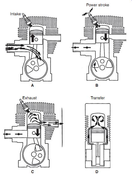
FIG. 1. Operating sequence of a third-port, loop-scavenged engine.
But the rule about the carburetor location does not necessarily apply to larger engines. Some European motorcycles had crankcase-mounted carburetors that fed through a rotary valve in the form of a partially cutaway disk, keyed to crankshaft. Model airplane engines and a few vintage outboards use a slotted crankshaft to the same effect.
Motorcycle engines often combine a third port with an integral reed valve.
The port controls timing and the reed prevents backflow through the carburetor. Although the reeds impose a pressure drop, midrange torque benefits.
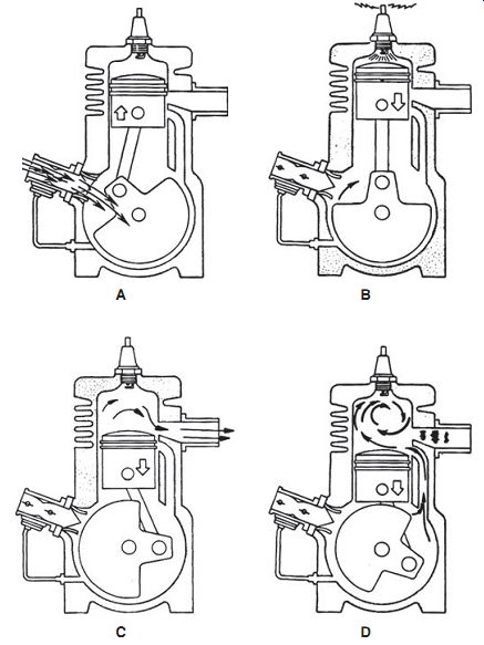
FIG. 2. Operating sequence of a reed-valve engine that in the example shown
employs loop scavenging. The small tube on the lower left of the drawing transfers
crankcase pressure pulses to the fuel pump. Deere and Company
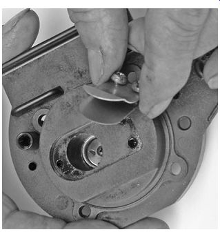
FIG. 3. Reed valves for handheld engines generally have a single pedal backed
by a guard plate to limit deflection.
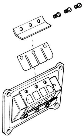
FIG. 4. Multiple pedals are standard on high-performance engines. While
there has been considerable experimentation with fiberglass, carbon fiber,
and other high-tech materials, spring-steel pedals appear to work as well as
any. Tecumseh Products Co.
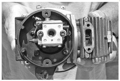
FIG. 5. Reed-valve engines mount their carburetors low on the crankcase.
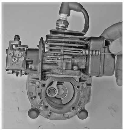
FIG. 6. Carburetors for third-port engines attach to the cylinder. Some
of these engines incorporate a reed valve in the third port.
Scavenging
Scavenging is the term for purging the cylinder of exhaust gases. Unlike a four cycle engine, which devotes a full stroke of the piston to clear the cylinder, a two-stroke must scavenge during the 100° or so of crankshaft rotation that the exhaust port remains open.
Blowdown
As the piston falls, it first uncovers the exhaust port and then, 5° or 10° of crankshaft rotation later, the transfer port. Blowdown occurs during this brief period that, at wide-open throttle, occupies no more than one or two thousandths of a second. In spite of its brevity, the blowdown phase is the primary mechanism for evacuating the cylinder.
The rapid opening of a port releases a high-pressure slug of exhaust gas that trails a low-pressure zone or wave in its wake. Cylinder pressure momentarily drops below atmospheric pressure. Responding to the pressure differential, the fresh charge moves through the transfer port to fill the cylinder. At part throttle, crankcase pressure is less than cylinder pressure. Were it not for the drop in cylinder pressure that accompanies blowdown, two-cycle engines would not run.
The need to accelerate exhaust gases quickly explains why exhaust ports for high-performance engines are rectangular rather than round. It also explains why we must keep these ports and mufflers free of carbon accumulations.
Exhaust tuning
When a high-pressure wave encounters a solid obstacle or an abrupt change in direction in the exhaust plumbing, it rebounds back to the exhaust port. These waves oscillate at the speed of sound and at a frequency determined by engine rpm. Where space permits, the length of the exhaust system can be tuned to reflect a high-pressure wave back to the exhaust port just as the cylinder fills to overflowing. The wave rams any fuel that spills out of the port back into the cylinder where it belongs. Of course, this works only over a narrow rpm range; at other speeds the wave can arrive early to the detriment of cylinder filling. In a similar manner, the intake tract can be tuned to maximize crankcase filling.
Spatial constraints make tuned exhaust and intake systems impractical for handheld equipment. About all that can be done is to arrange for a small boost from third- or fourth-order wave harmonics.
Charge scavenging
What exhaust gas remains in the cylinder after blow down must be scavenged by the fuel charge, which enters the cylinder at velocities as high as 65 m/s. Charge scavenging takes two forms, neither of which can entirely eliminate short-circuiting.
Short-circuiting
Short-circuiting is the term for the way incoming fuel escapes out the exhaust, as if one were trying to fill a leaky bucket. Most of the leak can be laid to symmetrical timing.
Because piston motion controls port timing, the timing is symmetrical around BDC. For example, an exhaust port that opens 60 crankshaft degrees before bottom dead center must remain open for 60° after BDC. The exhaust port opens a few degrees before the transfer port. Otherwise, the cylinder would not blow down and very little fuel would be delivered. But opening the exhaust port early means that it stays open throughout the entire fuel transfer process.
The open exhaust port acts as an escape hatch for incoming fuel. How much fuel escapes combustion varies with port geometry, rpm, and throttle position. An idling motorcycle short-circuits as much as 70% of its fuel out the exhaust. On average, two-stroke engines waste between 25% and 35% of their fuel in this manner.
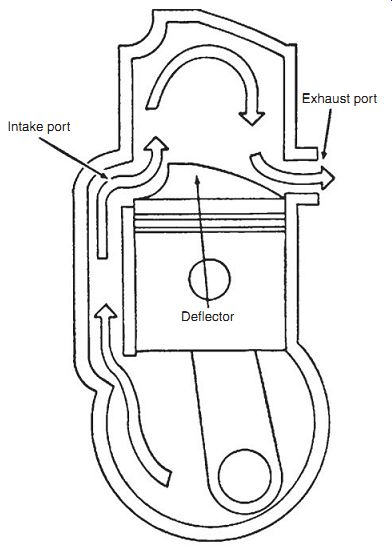
FIG. 7. Cross-scavenged engines have the intake port 180° opposite the exhaust
port. Incoming gases rebound upward off the deflector on the piston crown to
give some protection against short-circuiting.
Cross scavenging
Readers with long memories may recall the deflector pistons that were once standard ware on these engines (FIG. 7).
The fuel charge enters through a single transfer port, rebounds upward off the deflector, and drives residual exhaust gases out the exhaust port.
While this design works well at moderate speeds, at high speeds, the deflector can run hot enough to ignite the mixture. Nor does the simple trajectory made by the incoming charge impact the area just above the exhaust port, which remains a haven for exhaust gas. Other factors that mitigate against cross scavenging include the awkward shape of the combustion chamber and the weight penalty imposed by the deflector.
But the single transfer port simplifies foundry work, which explains why American outboard manufacturers were among the last to abandon this approach.
Loop scavenging
Current practice, based on work carried on in Germany during the 1920s, is to use loop, or Schn_rle, scavenging. Multiple transfer ports are arranged around the cylinder periphery with their exit ramps angled to impart swirl to the charge (Figs. 8 and 9). The miniature cyclone fills the whole combustion chamber, sweeping exhaust gases out ahead of it. In addition, the rapidly spinning mass of fuel and air has integrity, that is, it hangs together so that less fuel short-circuits.
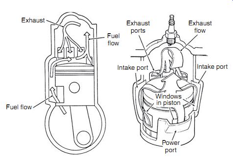
FIG. 8. In a loop-scavenged engine the fuel charge enters through multiple
transfer ports (called intake ports here) arranged around the periphery of
the cylinder. Port exit angles to give swirl to the charge, which reduces short-circuiting.
Windows in the piston skirt are an optional feature.
OMC
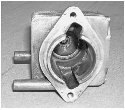
FIG. 9. This cylinder has what are sometimes called finger ports. That is,
the transfer ports are open to the bore along their whole length. Looking carefully
one can see the angled exit ramp at the upper end of lower port.
Displacement
We class ships by tonnage, houses by square footage, and engines by the volume the piston displaces as it moves between centers. All things equal, an engine should develop power in proportion to its displacement.
Displacement = bore × bore × number of cylinders × stroke × 0.7858
For example, the Tanaka series TBC-2501 has a 34-mm bore and a 27-mm stroke.
To perform the calculation, square the bore and multiply by the stroke:
34 × 34 × 1 × 27 × 0.7858 = 24526.39 mm^2
To convert to cubic centimeters, divide by 1000:
24526/1000 = 24.5 cc
To convert to cubic inches, multiply cubic centimeters by 0.061, which in this example gives 1.50 CID (cubic-inch displacement). To work the conversion the other way, multiply the CID by 16.387 to arrive at cubic centimeters.
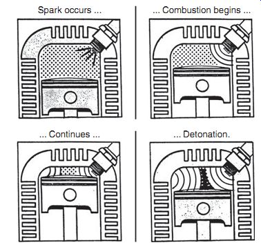
FIG. 10. As shown in this Champion Spark Plug drawing, detonation is a maverick
form of combustion initiated late in the process, after normal ignition.
Compression ratio
The compression ratio (CR) describes the amount of "squeeze" the piston applies to the air-fuel mixture prior to combustion. It is arrived at by dividing total cylinder volume, that is, the volume with piston at BDC, by the volume that remains when the piston rises to TDC. The latter figure is the clearance volume. Normally we take the manufacturer's word for CR, since determining the clearance volume can become a bit hairy, especially when a domed piston is fitted.
Some manufacturers express CR as just described, which is geometrically accurate and yields impressively high numbers. Others provide the effective ratio, calculating swept volume as the volume the piston transverses after the exhaust port closes. Obviously, there can be no compression with an open exhaust port. Effective CRs range from 6 to more than 8:1.
Up to a point, the higher the compression ratio the better. The limit is imposed by the tendency of the fuel, a tendency made worse by the presence of oil, to detonate. Normal combustion is an orderly process, initiated by the spark and moving out to fill the combustion chamber. Detonation occurs when the tag ends of the fuel charge, compressed and heated by the expanding flame front, suddenly explode (FIG. 10). Cylinder pressures skyrocket and, if detonation persists, the piston melts and crankpin bearings hammer flat.
In addition to cylinder compression, two-strokes also develop crankcase compression. Since the work of compressing the air/fuel charge prior to delivery absorbs energy that could be better used to turn the crankshaft, designers limit crankcase compression to between 1.3 and 1.6:1. Pressures rarely exceed 6 psi.
Torque and horsepower
Near the end of the eighteenth century, James Watt observed that a mine pony tethered to a turnstile could lift 550 lb one foot per second, or 33,000 lb per minute. Horsepower was a brilliant sales tool that put steam engines into a context that potential customers could understand. In metric notation, one horsepower equals 0.746 kilowatt (kW).
Torque, or the instantaneous twisting force on the crankshaft, is the active component of horsepower. One foot-pound of torque is a twisting force generated by a one-pound weight on the end of a bar one foot long.
Expressed metrically, 1 ft/lb equals 1.36 Newton meters (Nm) or 0.14 kilogram meters (kgm). To determine torque output, researchers mount the engine on a dynamometer and measure the braking force required to bring the engine to a halt. Once torque is known, the conversion to brake horsepower (bhp) is simple: bhp = (torque × rpm × 2 p)/33,000 Thus, an engine that produces 2 ft/lb of torque at 7000 rpm has a power output of bhp = (2 × 7000 × 2 × 3.14)/33000 bhp = 2.66 We feel the effects of torque as the ability of vehicles to accelerate and as the refusal of handheld tools to bog down under sudden loads. Internal combustion engines generally develop their maximum torque at about two thirds throttle.
hp = (torque × rpm)/5253
Peak hp occurs at full throttle or at some close approximation to it. The limiting factor is friction, especially friction between the piston rings and cylinder walls, which increases with speed even more rapidly than horse power.
The horsepower rating of engines remains a formidable sales tool that, in the absence of standards, can be easily manipulated. Reputable small engine manufacturers arrive at their horsepower numbers in accordance with the Society of Automotive Engineers (SAE) protocol J-1349. The test engine is tuned to laboratory precision, a process that includes de-carbonization after break-in, and its output measured at an ambient tempera ture 77°F (25°C) and an elevation of 100 m (328 ft) above sea level.
Since most engine makers follow this protocol, advertised horsepower can be used as a means of comparison between models and brands. But lab oratory levels of tuning boost horsepower beyond levels experienced in the field. As a practical matter, customers can expect no more than about 85% of the horses promised.
Pre-mix
Most modern two-strokes require 89 octane gasolines to prevent detonation. And the fuel should not be more than a few weeks old. As gasoline ages, the light hydrocarbons evaporate, leaving varnish and gums behind.
A fuel stabilizer, such as Briggs & Stratton Fresh Start, will preserve gasoline for as long as 24 months. However, stabilizers are not retroactive- stale fuel cannot be restored to its original state. Nor should gasolines with high alcohol (methanol or ethanol) content be used. Alcohol collects water that can promote corrosion and tends to cause oil to drop out of the pre-mix.
When water is a problem, the fuel can be strained through a chamois or a water-separator funnel available from marine-supply houses.
The safest choice is to follow manufacturer's recommendations for lube oil.
Approved lubricants for air-cooled two-strokes conform to JASC M345/FD and ISO-LEGD requirements. Some of these oils also carry Rotax snowmobile Test 2 certification.
It's interesting to note that Rotax warns against using pure synthetic oils in engines that stand idle for more than a few days at a time. The oil film left by synthetics drains off and exposes parts to corrosion. Some, but not all, manufacturers share the same concern. In-house lubricants from Husqvarna and Echo are blends of synthetic and traditional mineral oils.
The fuel-oil mixture as specified by the engine manufacturer (and not the oil refiner) should be used. Too little oil makes quick work of the engine; too much reduces the octane of the premix, scores pistons with carbon flakes and overheats catalytic converters. Most handheld equipment require a 50:1 mix, although some need more oil at 32:1. Vintage mosquito foggers, with their plain-bearing connecting rods, run at ratios of 16 or even 12:1.
Accurate measurement calls for a graduated flask and care to sight over the top of the oil and not the meniscus that clings to the sides of the flask.
Measure the amount of gasoline at the pump, pour the oil into the container, and shake vigorously. Since oil settles out over time, give the container a few shakes before refueling (Table 1).
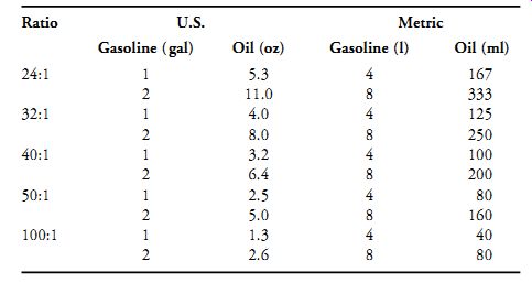
Table 1 Gasoline-to-Oil Ratios
Cooling
Only about 20% of the heat released during combustion is transformed into mechanical motion. The remainder goes out to the atmosphere by way of the exhaust and cooling system.
Conduction
Heat generated by combustion and friction produces molecular vibration in the surrounding metal, which passes from one molecule to the next in a process known as conduction. Since both thermal and electrical conduction depend upon the same mobile electrons, good electrical conductors, such as copper and aluminum, also make good thermal conductors.
The rate of heat transfer P depends upon:
• The difference in temperature (T2 hot - T1 cold), also known as the thermal gradient,
• Thermal conductivity k of the material,
• Area A of the material,
• The length L of the thermal path.
P = kA(T2 - T1)/L
To cool a cylinder, we want to use a material with good thermal conductivity (k), add fins to increase its area (A), and make the cylinder walls as thin as possible to reduce the length (L) of the thermal path. We can't do much about the thermal gradient, but it is already quite steep, since combustion temperature is more than an order of magnitude greater than the tempera ture of the surrounding air.
As a point of interest, the LeGnome rotary aircraft engine, widely used during the First World War, holds what must be a Guinness record for short thermal paths. Its steel cylinders were only a 0.5-mm (0.13-in.) thick. The fins provided the hoop strength necessary to withstand combustion forces.
In addition, each piston was fitted with a brass ring that flexed to accommodate cylinder distortion. It's not surprising that these engines required overhaul after as little as 10 hours of flying time.
Once heat has passed through the cylinder head and barrel, it must be dissipated into the atmosphere.
Radiation
Thermal radiation is an electromagnetic wave phenomenon that, in several respects, mimics the behavior of light. Infrared waves emanate at right angles from a warm surface. As temperature increases, the dominate wave frequency shifts to the visible spectrum. The progression goes from cherry red to white heat.
Radiation requires a target, preferably a dark object, to convert itself into heat. A wood stove warms one standing before it, while the surrounding air remains cold. And, as Russian peasants have known since time immemorial, a dark winter coat absorbs more heat than a light-colored one.
Table 2 lists emissivity coefficients for various states of aluminum at room temperature relative to the perfect emissor, or "black body." Such an object would have an emissivity coefficient of 1.
From this table, you can see that the rough and as-cast finishes on aluminum castings are pretty well ideal for heat transfer by radiation.
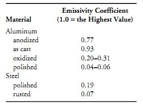
Table 2 Emissivity Coefficients
Convection
Convection, or the movement of thermal energy in fluids, can be demonstrated by the behavior of water heated in a pan. The water near the bottom of the pan rises and is replaced by cooler and heavier water. The same phenomenon occurs between adjacent cylinder fins: heated air moves away from the fins to be replaced by cooler air.
The cooling effect is intensified if we pressurize air with a fan and direct it over the fins by means of shrouding. Handheld and stationary engines employ this form of cooling, known as forced-air convection. Energizing air with a fan means that cylinder fins can be closely spaced and as thin as casting techniques permit. The fan forces air through the narrow interstices.
Motorcycles depend upon their forward movement to create a cooling draught. Free-air cooling eliminates the power drain of a fan, but works only if the machine is moving and moving without the assistance of a tailwind.
Because of the relatively low air velocity, fins are widely spaced and, in partial compensation for the loss of area, tend to be tall (FIG. 11). Radiation plays an important role in free-air cooling. When the vehicle is moving, radiation accounts for between a tenth or a sixth of the heat transfer. But if the bike is stationary, temperatures rapidly increase. Once past a certain threshold, the heat energy released by radiation goes up as the fourth power of the absolute, or Kelvin, temperature. K = 273.15°+°C. If cylinder-head temperature doubles from 300° to 600° (the equivalent of 328°), the rate of heat rejection is multiplied 16 times. It is no exaggeration to say that radiation makes free-air cooling practical.
Almost any engine can be made to run cooler. Cylinder fins should be clean and free of oil, which acts as a thermal insulator. Shrouds should fit tightly over the fins without air leaks. Unshrouded aluminum castings radiate better with a light coat of paint. Some professionals use Rustoleum black enamel, cut with gasoline to eliminate the gloss. But color has less of an effect than the type of paint used. Light colors are used on the interior surfaces of microwave ovens. Epoxy and urethane paints deliver 90% or more of black body radiation at room temperatures; enamels do less well at around 83%.
Emissions
FIG. 11. The Ficket & Sachs 505 depends upon the forward motion of the
moped for cooling. Because the cylinder is horizontal, the fins run longitudinally
along the length of the barrel.
On the face of it, concern about emissions from thimble-sized engines seems frivolous. But those who make their livings with handheld tools might see things differently. Or at least, they should. According to the California Air Resources Board (CARB), an hour of weed whacking is the emissions equivalent of driving 834 miles in a modern automobile. It's also true that two-cycle exhaust has a serious impact upon heath in the developing world. An estimated 70 to 100 million motorcycles, mopeds, tuk-tuks, and tricycles vie for space on the streets of Asiatic cities.
* These engines are believed to account for 70% of India's hydrocarbon emissions, 46% of the nation's carbon monoxide emissions, and a large fraction of its particulate matter.
The emissions data presented in the following discussion are based on a European Commission study of three two-stroke engines (one trimmer and two chainsaws) and two four-stroke trimmers.
Hydrocarbons
Short-circuiting helps explain why the two-stroke engines produced as much as four times more hydrocarbons (HC) than their four-stroke counterparts. Rich mixtures exacerbate the problem. Other sources of HC include quenching, as the flame front cools in contact with metal surfaces. The worst offender in this regard is the narrow crevice between the piston and the cylinder bore in the area above the upper ring.
The primary effect of HC is smog, although several mutagenic and carcinogenic compounds are present in the mix.
Carbon monoxide and carbon dioxide
Carbon monoxide (CO) is an odorless and colorless gas that, when inhaled, displaces oxygen in the blood stream. Low exposures result in nausea and headaches; higher levels of exposure are lethal.
The two-strokes in the European tests produced about the same level of CO as the four-strokes. Carbon monoxide results from incomplete combustion. When sufficient oxygen is present, carbon combines with a second oxygen molecule to produce carbon dioxide (CO2), the infamous global warming gas. Other studies have demonstrated a powerful linkage between CO and carburetor settings. Rich mixtures can emit an order of magnitude more CO than extremely lean mixtures.
Oxides of nitrogen
Oxides of nitrogen (NOx) (rhymes with "socks") is a blanket term for the various oxides of nitrogen that react with the environment to cause smog, ground-level ozone, and acid rain. Fortunately, two-cycle engines do not attain the high combustion temperatures required for large-scale NOx formation. In the European Commission tests, two-strokes produced about half the oxides of nitrogen as the four-strokes.
Particulate matter
Particulate matter (PM) is the nongaseous component of exhaust, consisting of tiny spherules of carbon, loosely bound in clusters or chains. Spewed out the exhaust like shotgun pellets, these solids imbed themselves deep into lung tissue where they pose a serious heath hazard. In addition, PM particles often coalesce around a powerful carcinogen known as the soluble organic fraction (SOF) of poly-aromatic hydrocarbons. According to the American Lung Association, PM inhalation from all sources accounts for 50,000 deaths annually in the United States.
The European study did not measure particulate matter, since it is not currently regulated. However, Finnish researchers found that the volume of PM emitted by a 46-cc, two-stroke chainsaw "was relatively large compared to particulate emissions from automobiles."* More critical was their finding that 95% of these solids fell into the SOF category. Over-oiling should be avoided: a 6% oil-gasoline mix generates three times more PM than a 2% mixture.
Regulations
As far as the North America is concerned, the impact of emissions standards on two-cycle engines is pretty well confined to garden equipment and other non-road applications. Almost no road-legal two-stroke motorcycles survive in this market.
In 1995 CARB cut emissions levels by 30% for non-road small engines sold in California under what came to be known as Tier 1 regulations. Several north eastern states followed California's lead. Only three pollutants were of concern- CO, NOx, and HC-with the latter two combined into a gram per kilowatt hour (1 kW/h = 1.32 hp) limit.
Two years later, the Federal Environmental Protection Agency (EPA) followed up with its own Phase 1 rules that reduced emissions for non-hand held engines sold elsewhere in the country by 32%. Although several manufacturers objected, Tier 1/Phase 1 regulations caused no great hardship. Carburetors were calibrated leaner and restrictor caps were fitted to the mixture-adjustment screws to prevent tampering.
CARB then announced that it would reduce small-engine emissions by another 80%. Tier 2 was to come into effect in 1999. The EPA proposed similar limits for Phase 2, but softened the impact by spreading compliance over a 3-year period beginning in 2002. Both agencies permitted manufacturers to offset noncompliant engines with cleaner engines, bank emissions credits, and trade credits with competitors. Tier 2/Phase 2 also includes a provision for a second emissions test to assure compliance as equipment ages. The "Emission Compliance Period" equates with the useful life of the product and ranges from 50 to 500 hours.
The Portable Power Equipment Manufacturers Association (PPEMA) saw these regulations as an attack on their base. An 80% reduction in emissions seemed unrealistic, especially in view of the profit squeeze imposed by discount houses.
Lowe's, Home Depot, Walmart and the like account for nearly three-quarters of gar den equipment sales. An Echo manufacturing executive would later confide to Fortune magazine that the struggle cost him his hair and 35 lb of weight gain. The trade group rolled up its collective sleeves and went to work on the political front. The initial target was CARB. PPEMA asked for a 50% cap on emissions, a figure that could be achieved with conventional technology.
But Tanaka and RedMax had another agenda. Thanks to their recently developed stratified-charge engines, these companies were confident that they could meet the 80% cap. During a 10-hour meeting they urged CARB to hold firm. And hold firm CARB did, but as a sop to PPEMA, delayed implementation of Tier 2 for a year.
Some two-stroke makers failed to meet these standards and could no longer remain in business. McCulloch, once the king of chainsaws, filed for bankruptcy in 1999 and is now in the hands of a Taiwanese company.
Efforts to mollify or delay EPA Phase 2 regulations met the same fate.
According to industry insiders, the battle was lost, in great part, because of the deflection of John Deere and Co. Initially Deere had opposed Phase 2, but then lobbied to keep the regulations intact. Deere had its own version of stratified scavenging. In disarray, PPEMA closed its doors in 2001. Most of its members migrated to the Outdoor Power Equipment Institute.

Table 3 U.S. Emissions Standards for Small Engines in Handheld and Nonhandheld
Applications Table 1-3 U.S. Emissions Standards for Small Engines in Handheld
and Nonhandheld Applications (Continued )
EPA Phase 3, scheduled to take effect in the 2012 model year, will further tighten emissions for lawnmowers and portable generators. And following CARB's lead, the EPA will impose evaporative limits, which require non permeable fuel tanks and lines.
The European Union has signaled its intent to regulate CO2 emissions from all sources, including small engines. As things stand today, the only way to limit carbon dioxide is to reduce fuel consumption.
Ever-tightening regulatory constraints leave manufacturers with two options: switch to four-cycle engines or else figure out ways to clean up the traditional product (Table 1-3). The four-cycle option Ryobi invested $10 million in the four-cycle engine that powered the first string trimmer certified under CARB Tier 2. The company subsequently collaborated with RedMax-Komatsu Zenoah to produce a heavy-duty version of the engine. Honda, recognizing the opportunity, entered the market with its overhead cam GX22 and GX31. Briggs & Stratton followed with its 34-cc Fource engine. Thanks to mist-type oiling systems and diaphragm carburetors, these little four-bangers operate at any angle.
But four-cycle micro engines have their detractors. According to a spokesman for Robin America, a four-stroke 25-cc engine is, on average, 1.1 lb heavier than the equivalent two-stroke. And that's a conservative estimate: the 29-cc Craftsman model 79197 four-stroke trimmer tilts the scales at 20 lb, less fuel and oil. In contrast, a Husqvarna two-stroke trimmer of the same displacement weights 10.6 lb. The weight penalty comes into sharper focus when we realize that these little four-strokes develop 30 to 50% less power than equivalent two-strokes.
The valve gear required by four-stroke engines consists of 25 or 30 parts, most of which require precision machining and heat treating. These parts add as much as $50 to the retail price, compromise reliability, and complicate repairs. As Henry Ford used to say, "Parts you don't have, can't break." Two-cycle lubrication is automatic, once the fuel is mixed. But four-cycle engines need frequent oil changes and level checks, chores that contractors cannot depend upon their field personnel to perform. In addition, there are reports of problems with these new engines when operated off the horizontal.
But the advent of hybrids, which combine some of the best features of two-strokes with superior fuel economy and less pollution, shifts the balance.
Hybrids
The STIHL 4-Mix used to power several of the company's garden tools, combines crankcase induction with four-stroke operation. The dry crankcase permits the engine to run at any angle and eliminates worries about oil levels and change intervals. And the four-stroke cycle, which allocates a full piston stroke to scavenging, significantly reduces HC emissions without the need for a catalytic converter. As a bonus, 4-Mix engines deliver 30% better fuel economy and 14% more torque than equivalent two-strokes.
Figure 12 shows the general layout. The upper crankcase, cylinder barrel, and head are integrated into a single aluminum casting. Overhead valves operate from a single cam lobe, a feature that reduces engine size and weight (FIG. 13). The cam also incorporates an automatic compression release.
Oiling is accomplished by patented, two-stage process. As the piston rises toward TDC, it creates a partial vacuum in the crankcase (FIG. 14). The fresh charge, consisting of a 50:1 mix of fuel and lube oil, enters through the inlet pipe (1) and bypass port (2) and passes over the cylinder head on its way to the crankcase. En route, the fuel charge wets all moving parts, including the critical camshaft lever.
Cleaner two-cycle exhaust
Survival of the two-stroke engine depends upon finding ways to limit HC and CO exhaust emissions. Currently two approaches are used: stratified charging and exhaust after treatment.
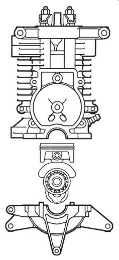
FIG. 12. The horizontally split crankcase is a welcome feature that provides
easy access to rotating components.
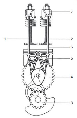
FIG. 13. A single cam lobe (4), driven at half speed through the crankshaft
gear (3) and through a pivoted lever (5), pushrods (6), and rocker arms (7)
actuates the exhaust (1) and inlet valves (2). Generously sized drive gears,
coupled with anti friction bearings, are designed for durability.
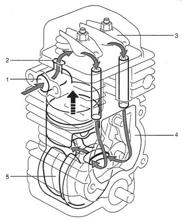
FIG. 14. The 4-Mix draws fuel into the crankcase through the bypass port
as the piston rises. The downward movement of the piston pressurizes the crankcase.
Oil impregnated fuel then leaves the crankcase, lubricating the critical valve-gear
parts for a second time (FIG. 15).
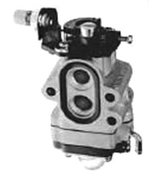
FIG. 16. The Walbro WYA carburetor features a 12-mm bore, an adjustable
idle jet, and can be fitted with an accelerator pump.
While designed for stratified charge two-stroke engines, this carburetor can also be adapted to four-strokes.
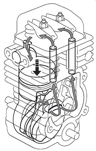
FIG. 15. As the piston falls, the pressurized fuel mixture flows out of
the crankcase and back to the intake pipe for induction into the cylinder.
In the process, moving parts are again wetted.
Stratified scavenging
One way to sanitize two-strokes is to purge the cylinder with air before introducing fuel. As developed by RedMax-Komatsu Zenoah, stratified scavenging employs a Walbro WYA double-barreled carburetor, with one bore for air delivery and the other for the air/fuel mixture (FIG. 16). The RedMax Stage 1 incorporates two transfer ports, each of which is fitted with a reed valve that opens to the air-only carburetor bore. An additional reed valve connects the second, or fueling, carburetor bore with the crankcase.
As the piston uncovers the exhaust port, residual gases blow down and leave a vacuum behind in the cylinder. Transfer-port reed valves open to admit purge air from the carburetor. Meanwhile the falling piston builds pressure in the crankcase and in the transfer ports. Within 10° or so of crank shaft rotation after blowdown, sufficient pressure is developed to close the transfer-port reed valves. Air no longer enters the cylinder, which then fills with the fresh mixture from the crankcase.
According to RedMax, stratified scavenging reduces HC emissions by as much as 80% and, under optimum conditions, boosts thermal efficiency by 51%.
On the other hand, cylinder filling suffers because some scavenge air remains in the cylinder after the exhaust port closes. The prototype version developed slightly less power than a reference engine with conventional porting.
NOx emissions, fueled by the additional oxygen, showed a small increase.
In 1998 the RedMax became the first production two-stroke to receive CARB Tier-2 certification. That year also saw the certification of a proof-of-concept engine, the result of a $10-million collaboration by Tanaka and CARB.
Unlike the EPA, California regulators take an active part in the development of technology.
Surprisingly enough, the Strato-Charged RedMax encountered buyer resistance. Potential buyers interpreted the unobtrusive exhaust note as evidence of lack of power. But reduced fuel consumption, on the order of 34%, made converts. The big breakthrough came in 1999, when STIHL purchased 60,000 of the engines for the California market.
Catalytic converters
The CARB Tier 2 Tanaka Pure-Fire 260PF trimmer/brush cutter employs a catalytic muffler and a unique induction system. The engine has a 33-mm bore and a short 28-mm stroke for a displacement of 24 cc. With a dry weight of only 12.4 lb and a power output of 1.3 hp at 11,000 rpm, the 260PF has one of the best power-to-weight ratios in the industry.
At first glance, the PureFire could pass for any other piston-ported engine. Air and fuel are drawn into the crankcase during the upstroke and forced out through transfer ports on the downstroke. Fuel and air move out of the crankcase and into a channel that leads to the transfer ports. A small diameter orifice connects the crankcase cavity with the transfer-port feed.
This orifice gives velocity to the charge, which absorbs heat in its journey to the transfer ports. Velocity and heat assist in fuel atomization, a precondition for efficient combustion. The photo on the cover of this guide illustrates Purefire gas flow.
HC and CO emissions that survive are oxidized in the catalytic muffler.
The catalyst consists of a thin veneer of platinum, palladium, or rhodium applied over a ceramic or metal matrix. A two-way converter, that is., one that oxidizes HC and CO, is all that's needed. NOx emissions do not present much of a problem for carbureted two-strokes.
In the presence of heat, the converter oxidizes hydrocarbons into carbon dioxide and water. The basic reaction is HC + O2 ? CO2 + H2O.
This exothermic reaction boosts exhaust temperatures to 1000°C and higher.
Carbon monoxide combines with oxygen to form carbon dioxide:
CO + 1/2O2 ? CO2.
Other reactions involving CO release water and hydrogen.
The first version of PureFire technology-the 250PF-relied upon the converter to scrub 40% of exhaust emissions. The recently introduced 260PF cuts the percentage to 30% through a redesign of the combustion chamber.
Consequently, the converter runs cooler and should last longer.
A catalytic converter intensifies maintenance requirements. Rich mixtures resulting from improper carburetor adjustments or dirty air filters must be avoided. Converter burnout occurs at 1400°C or about 300°C more than nor mal for high-output engines. Excessive oil or the wrong type of oil fouls the catalyst. And finally, silicone adhesives or carburetor cleaners containing lead, phosphorous, or silicone must not be used. But, even with these pre cautions, converters are sacrificial items that need periodic replacement.
While I do not have figures for handheld equipment, the Indian government estimates that catalytic converters for light motorcycles have a useful life of only 15,000 km.
Marks of quality
Designers of small motorcycle engines are a conservative bunch and rarely deviate from a pattern that was established during the 1930s. Almost without exception, these engines have vertically split crankcases, ball main bearings, one-piece connecting rods, and loop-scavenged cylinders. Since design is frozen, variations in quality come down to the choice of materials and the precision of manufacture. Japanese and European makes are the obvious leaders, with Chinese and East Indian bikes trailing far behind. While many readers might protest, the EPA calculates the useful life of small motorcycles (those displacing between 150 and 169 cc) at 12,000 km (7456 mi).
Designers of handheld equipment are much more flexible, in part, because the machines are tailored to very different markets. It's possible to buy a chainsaw for $150 or weed trimmer for half that. But the money saved will soon be spent on repairs. Midrange handhelds cost, on the average, around $300 per unit. Expect to pay $600 or more for professional quality two-stroke equipment. In no particular order, the top brands include names such as STIHL, RedMax, top-line Echos, Shindaiwa, Tanaka, Husqvarna, Dolmar, and Jonsered. Find out what local landscape contractors use, since quality involves more than the brand name. You want a machine from a nearby dealer, who has a good parts inventory and who honors warranty claims.
What is the useful life of handheld equipment? Manufacturers are coy about this question, but we do know that the design life--the life engineers try for--is 1000 hours for professional quality tools. Echo insists that their engines, which are not dramatically different than other upper-echelon products, have a design life of 1200 to 1500 hours or more. In the writer's experience, low-end, mass-marketed tools can self-destruct in as little as 50 hours.
The factory warranty period reflects how well the design life goals are achieved. Good-quality garden and construction tools carry a warranty of 2 years in private use, 1 year commercial, and 90 days rental. Some offer longer periods and certain components such as ignition modules and drive line parts may be covered for the life of the equipment. Chainsaw warranties typically extend for a year of private use.
Another indication of the way manufacturers judge the longevity of their products has come about because the EPA insists that exhaust emissions be tested twice, once when the engine is new and a second time at the end of its useful life. According to the rule, published in 40 CFR, Section 1, 90.105, manufacturers must certify the time of the second test. The choice is between 125, 250, and 500 operating hours. Useful life is calculated on the basis of engineering evaluations of wear, surveys of engines in the field, customer complaints and other hard data. No manufacturer has opted for the 500-hour test.
Design features to look for are:
• Two main bearings, one on each end of the crankshaft. Cheaper and almost certainly less durable engines use crankshafts cantilevered off of a single bearing (FIG. 17).
• High-quality engines, such as the STIHL, RedMax, and Tanaka employ replaceable crankshaft seals that are more reliable and easier to replace than bearings with integrated seals (FIG. 18).
• Chrome-plated or Nikasil-coated cylinder bore. Some manufacturers merely chrome the piston.
• Stress-relieved cylinders. Tanaka and a few other manufacturers allow cylinders to age before final machining.
• Thin, closely packed cylinder fins for efficient cooling.
• Four cylinder-to-crankcase bolts, rather than two (FIG. 18). Two hold down bolts are a proscription for air leaks, although it must be said that the RedMax two-bolt arrangement with locking tabs gives no trouble.
• Two compression rings. Low-end products get by with one.
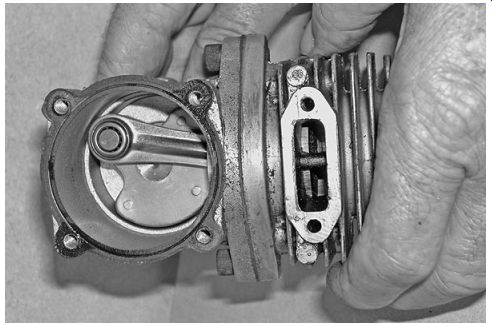
FIG. 17. Hanging the crankshaft off a single main bearing dramatically reduces
costs. The vestigial crankshaft requires little machining and the crankcase
cover can be made of plastic.
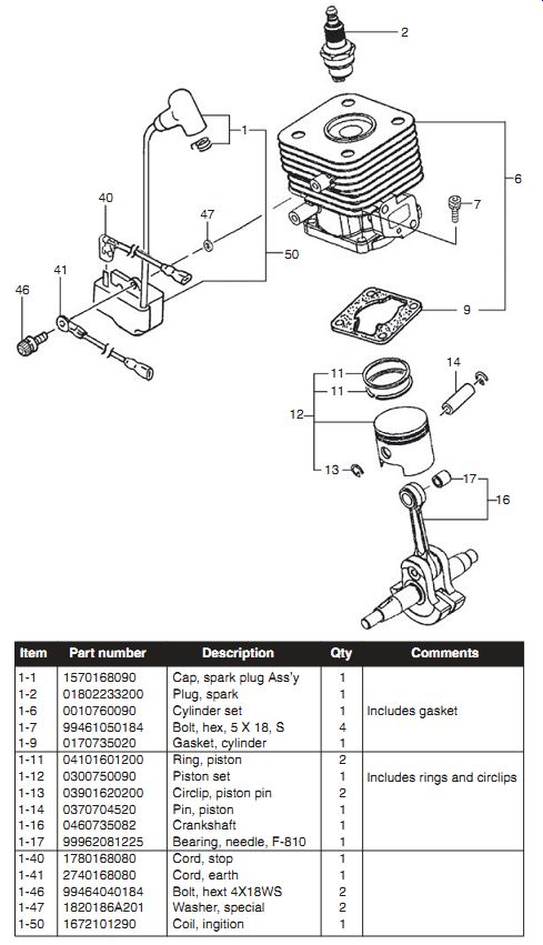
FIG. 18. Tanaka 260 PF is an example of design quality. Hitachi Koki USA
• Wrist pin with a caged roller bearing and thrust washers. Few, if any, low-priced engines incorporate thrust washers. One manufacturer goes so far as to eliminate the circlips that prevent the wrist pin from walking into the cylinder bore.
• One-piece connecting rod as opposed to a sheet-steel stamping.
• A flywheel massive enough to smooth compression resistance during cranking.
• A digital ignition module that eliminates kickbacks during starting.
There is also the question of how power is transmitted through 90°, which is a requirement for most handheld tools. The easy way is to make the transition is mount the cutter head on a curved shaft. A flexible cable, a kind of jumbo speedometer cable, transmits power. The cable whips and quickly destroys its bushings. Quality machines employ a solid steel drive shaft, about 7 mm in diameter, and bevel gears at the cutter head. The ends of the shaft should have proper splines (D-shaped or squared ends need not apply) and ride on ball bearings. Oil-lite bushings are a distant second choice and nylon bushings are hardly worth mentioning.
But be aware: Some midmarket trimmers have the prerequisite gear box, but drive through a flexible cable.
The learning curve
Things learned from working on automobiles and four-stroke lawnmowers do not always apply to two-strokes. This is why small-engine shops usually have a resident two-stroke guru, who can be called on when simple fixes fail.
The basic problem is getting rid of the heat generated by engines that fire every revolution. Catalytic converters add to the heat load as does the scale effect. Because of reduced surface area, the smaller the engine, the more heat retained.
Combine heat with the high oil consumption of two-cycle engines and we have a recipe for carbon production. After long use, carbon deposits in the exhaust port and muffler throttle the engine. Carbon also collects in the ring grooves, where it robs the rings of their elasticity. If rings cannot flex, they cannot seal. Large fragments of carbon, embryonic diamonds, can break off and score the bore and piston. Most scoring occurs in areas adjacent to the exhaust port, which runs hot and sees little by way of lubrication. As a point of interest, the bridge-the knife-like rib running vertically between the exhaust ports-is the hottest part of the engine. But without a bridge, the rings would expand to fill the port and snag.
Heat also distorts plastic shrouding, causing air leaks and converting fuel lines into something resembling uncooked spaghetti. Compromised fuel lines can leak fuel or air.
Another factor to be aware of is the sensitivity of the cylinder/ring seal.
Wear and scuffing that go unnoticed on larger engines take on major importance when cylinder diameters are reduced to 30 or 35 mm. The ring seal also pressurizes the crankcase, a function that becomes critical during starting, when rpm is low. Consequently a small two-stroke needs a minimum of 90 psi cranking compression. A four-stroke can be persuaded to run with 60 psi. Crankcase compression also depends upon the integrity of the crankshaft seals and, when fitted, the reed valve.
And finally, there is the matter of carburetors. In order to operate at large angles off the horizontal, two-stroke engines have diaphragm carburetors with integral fuel pumps. These carburetors are a world apart from the float type units found on most four-cycle engines.
To summarize, the differences between two-stroke gurus and ordinary mechanics are that gurus appreciate the importance of cylinder and crankcase sealing, check that rings are free to flex, look on fuel lines with suspicion, and have experience with diaphragm carburetors.
Long-term storage
At least half of the problems associated with two-cycle engines come about because of improper storage. Before putting an engine up for any extended period,
• Remove the shrouding and clean the cylinder fins with a brush and solvent.
• Remove debris from the cutter head, blade, and drive sprocket.
• Inspect and, if necessary, clean the flame arrestor screen that will either be inside the muffler or clipped to it.
• Drain the fuel tank and run the engine at idle until it stops. Do not open the throttle, since running dry of fuel also robs the engine of lubrication.
• Remove the spark plug and pour a teaspoon or so of oil into the cylinder. Slowly turn the engine over several revolutions to distribute the oil. Replace the spark plug and reconnect the ignition lead.
• Safely discard fuel that will not be used during the next 3 to 4 weeks.
Inspect the fuel container for rust or varnish build up.
Safety By their nature, gasoline engines pose risks. The fuel is highly volatile, mufflers and catalytic converters run hot, exposed parts revolve at high speeds, and, when confined in a closed space, the exhaust can be lethal. These dangers are exacerbated when the engine is handheld or strapped to one's back.
Gasoline
A U.S. gallon of gasoline contains 125,000 Btu, which represents more heat energy than an equivalent weight of TNT. At temperatures above 45°F (7.2°C), open or leaking gasoline containers give off vapor. Should it find an ignition source, the vapor trail acts as a fuse to convey the flame back to the container.
Store fuel in an approved safety container-not a plastic jug. The container should be tightly sealed and filled to no more 90% of capacity to allow for heat expansion. Gasoline and other flammables should be stored in a locker, remote from the shop and house.
Allow at least 5 minutes for the engine to cool before refueling or opening a fuel line. If working outdoors is impractical, make certain the shop is well ventilated and that no ignition sources are present. Obviously one would not weld, grind, or smoke in the presence of fuel vapor, but one should also be aware that any spark, as from switching on a light, can become an ignition source. Before starting an engine after adding fuel, wipe up any spills, allow ample time for evaporation, and position the fuel container at least 10 ft (3 m) from the machine.
Although many mechanics prime engines by injecting gasoline into the carburetor or cylinder, many of the same mechanics are admitted to hospital emergency rooms for burn treatments. When an engine must be primed to verify fuel delivery, use aerosol carburetor cleaner, never gasoline. Work outside, spray a tiny amount of cleaner into the air intake, and replace the air filter element before starting. The air filter acts as a spark arrestor.
Do not use gasoline as a cleaning fluid. A heavier hydrocarbon, such as kerosene or "safety solvent" works about as well and eliminates much of the fire and exposure hazard. Gunk, available in aerosol cans from auto parts houses, does an excellent job of removing grease. But no solvent is entirely free of hazard; California health authorities classify Gunk as a carcinogen.
And finally, equip the shop with at least one Class B fire extinguisher.
Water merely spreads gasoline and oil fires.
Carbon monoxide Never operate an engine in an enclosed space. When inhaled, carbon monoxide (CO) displaces oxygen in the bloodstream. Low levels of expo sure result in nausea and headaches; higher levels are lethal.
Rotating parts
The business end of cutting and drilling tools present obvious hazards, and string trimmers, some of which turn 11,000 rpm, are by no means innocuous. Complement the safety instructions in the owner's manual-which can never be complete-with common sense.
Be aware of the possibility of accidental starting when carrying out ser vice work. An engine secured in a vise by its crankshaft can, and sometimes does, start when rotated. If the shrouding is in place, the spark plug will not be accessible to a hammer; about all one can do is to clear the area and wait for the tank to run dry.
Open sparks
While we routinely test for ignition voltage by arcing the high-tension lead to ground, this procedure entails risk. The safer approach is to use a shielded ignition tester, as described in the "Troubleshooting" and "Ignition systems" sections. These testers confine the spark behind a transparent window.
Recalls
The U.S. Consumer Products Safety Commission website at www.cpsc.gov performs a valuable service by alerting mechanics and owners to safety hazards that, because they are statistical in nature, might otherwise go unnoticed.
Chainsaws have been recalled because of fuel leaks and flywheel disintegration. The muffler support strap on RedMax EB 6200, EB 7000, and EB 7001 backpack blowers has, on several occasions, torn away from the muffler, leaving a hole that diverts hot exhaust gases toward the plastic fuel tank.
Conclusion
Now that we understand how these engines work and something about the forces that have shaped them, it's time break out the tools and get to work.
The next section deals with troubleshooting, the critical skill that separates real mechanics from part changers.
Prev. | Next
Home Article
index top
of page