This section describes how to service clutches, belts, shafts, and other power-transmission components. This information will also be helpful to readers who want to adapt small engines for other uses.
Centrifugal clutches
A centrifugal clutch, the mirror image of a drum brake, uses friction to transmit power. Figure 1 illustrates the typical layout, consisting of a pair of shoes restrained by a coil spring. The shoe assembly keys to the crankshaft and is secured by a nut that may have left-hand threads. The drum rides on a needle bearing or, on less expensive machines, a brass bushing ( Fig. 2).
The level of sophistication increases for chainsaws and other heavily used tools ( Fig. 3). Clutch-in speed varies with the application, but is usually near the torque peak of the engine. Reducing spring tension or adding weight to the shoes lowers the clutch-engagement speed.
When overloaded, a centrifugal clutch behaves almost like a variable speed transmission: engine rpm drops, the clutch disengages, rpm recovers, and the clutch again engages. On- and off-again engagement does, how ever, generate large amounts of heat.
Clutch failure is usually the result of overheating from application of greater loads that the engine can manage or that the clutch was designed for ( Tbl. 1).
Builders of trimmer- and chainsaw-powered bicycles, mini-bikes, and other one-off creations often encounter clutch problems. OEM centrifugal clutches cannot tolerate the loads. Until recently, the only option was an aftermarket clutch designed for four-stroke engines with crankshaft diameters of between 5/8 and 1 in. One had to bush the clutch down to the size and play with spring tension to match two-stroke torque characteristics. But that has changed: Comet Industries now offers a 3/8-in.-bore centrifugal clutch two-stroke engines of between 0.5 and 2.5 hp.
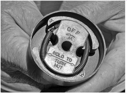
FIG. 1. Two-shoe clutch typical of garden tools.
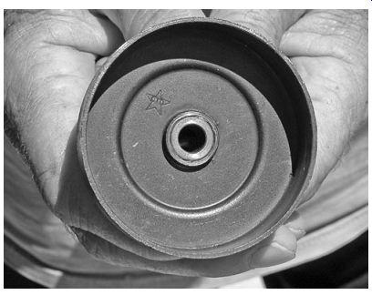
FIG. 2. When the clutch drum rides on a bushing, frequent lubrication is
required.
----------

Tbl. 1
Clutch Malfunctions and Their Probable Causes
Symptom Probable Cause
Failure to disengage
Weak or broken shoe springs
Idle speed set to high
Sticking shoe pivots
Slip under load Oil on friction surfaces
Worn shoe linings
Worn drum
Overloading
Radial (side-to-side) Worn drum bearing play on drum
-------------
Repairs
Repairs are not difficult, once we realize that most of these clutches secure with left-hand threads. Also, be aware that starting an engine without the clutch drum in place invites serious injury. The shoes, no longer restrained by the drum, become projectiles. And even with the drums in place, clutches have been known to explode. Racing go-karts have their clutches encased in heavy-gauge steel guards.
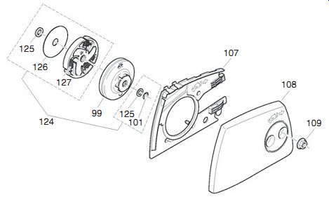
FIG. 3. The clutch for a Dolmar chainsaw is more sophisticated than those
pictured previously. Major components are the drum (99) and shoe and spring
assembly (127).
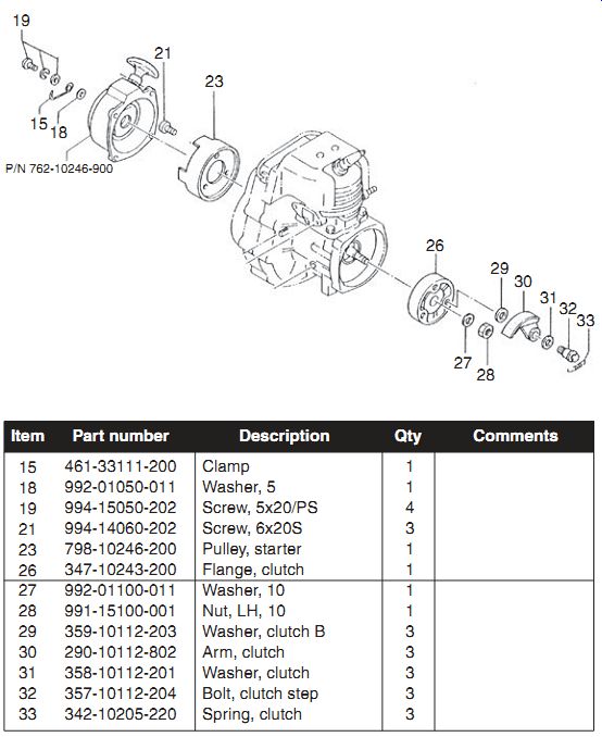
FIG. 4. Triple-shoe clutch used on the Tanaka TLE 550 edger. The shoes are
lined to improve performance and reduce drum wear.
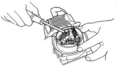
FIG. 5. Springs pry off. Replace the springs if blued, distorted or if the
clutch refuses to disengage or engages early.
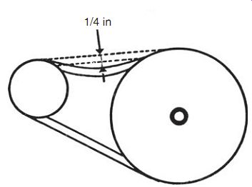
FIG. 6. A quarter inch of deflection should be sufficient for most applications.
Follow this procedure:
1. Remove the engine from the frame. On some designs, the clutch drum remains with frame as the engine is detached.
2. If the hold-down nut must be removed for access, determine the thread direction. Some left-hand-threaded units are marked; others can be identified by close inspection. Remove the nut with a power impact wrench. When hand tools are used, lock the crankshaft with a length of nylon rope fed through the spark-plug port, as illustrated back in Fig. 2.
3. Verify that the driven element can be turned by hand. If not, deter mine the cause.
4. Carefully examine the clutch drum for cracks, heat checks, and scores.
Replace as necessary.
5. The shoes may be restrained by an encircling garter spring or, if pivoted, by individual springs (33 in Fig. 4). Pry the springs off with a screwdriver ( Fig. 5). Do not be surprised to find that the springs have lost tension because of overheating.
6. Friction surfaces must be dry, if the clutch is not to slip. A leaking pto crankshaft seal will oil the clutch.
7. Inspect shoes for wear. Heavy-duty shoes may be lined with Kelvar or another non-asbestos friction material.
8. Remove the fastening hardware and lightly grease the shoe pivots.
V-belts
A V-belt transmits power by wedging its angled sides into the pulley grooves. As the belt wears, it sinks deeper into the pulley, or sheave.
Eventually the belt rides on the base of the groove, defeating the wedging action. Very little torque is transferred.
Sheaves "dish" in service, a condition that can be detected with a straightedge.
Any light between the straightedge and the flanks of the groove is grounds for replacing the sheave. Extreme wear sends the belt into base of the groove.
Adjustment
Verify that pulley shafts are dead parallel and align pulleys with a straight edge so that the belt centers in the grooves.
Belt tension is difficult to generalize about since the correct tension depends on multiple factors, such as the arc of contact on the smaller pulley, belt width, and distance between pulley centers. Too little tension results in belt flap and slippage; too much tension costs power and loads bearings. As a very broad rule, belts for small-engine applications should deflect 1/4 in. between centers under moderate thumb pressure ( Fig. 6). Retest after several hours of operation-all V-belts stretch.
Troubleshooting
Tbl. 2 lists belt maladies and their causes.
Belt sizing
The 40° included angle on V-belt sheaves is constant, but other aspects of belt design vary. DIN (German Institute for Standardization), ISO (International Standards Organization), and RMA (Rubber Manufacturer's Association) each have their own standards for belt profiles and for the way lengths are expressed ( Tbl. 3).
Purchase the exact replacement by brand name, especially when dealing with metric belts. Interchange lists are never exact. When dimensions are unknown, measure the sheave groove to determine width and use one of the Internet calculators to arrive at the length.
Measure the sheave center-to-center distance with the sheaves as closely together as the adjustment permits.
A belt running on fixed pulleys has some ability to multiply torque. The pulleys in Fig. 7 have identical diameters. But effective diameters depend upon belt tracking. Under load, the lower side of the belt tenses and the upper side relaxes. The belt buries itself deeper into the driven pulley and moves outward on the drive pulley. Torque is multiplied.
Tbl. 2
Belt Malfunctions and Their Causes
-----------
Belt Symptom Probable Cause
Excessive wear Sheave grooves worn
Sheave misalignment
Sheave diameter too small for the amount of power transferred Rough sidewalls Slippage caused by misalignment or worn sheaves Break in fabric cover Prying belt over sheaves during installation Cracks in base of belt Insufficient tensioning Slippage Slip burn (localized cauterization) Slip during starting Swelling or softening Oil contamination Flap Insufficient tension Unbalanced sheaves Belt turns over in sheaves
Misalignment
Sheave wear
Insufficient tension
Worn-out belt
------------
Tbl. 3 V-Belt Nomenclature and Profile
Belt-driven torque converter
While self-induced torque multiplication is always welcome, the effect is minimal. Serious torque multiplication requires a torque converter. These devices act as centrifugal clutches to disengage the belt at idle and, at higher engine speeds, provide stepless shifting. Ratios blend seamlessly, which gives the feel of steam traction and extends the life of chains, sprockets, and other downstream components.
Belt-driven torque converters are an excellent choice for home builders, who want to give their mini-bikes, scooters, and go karts flexibility without the expense and complication of gearboxes. High-tech versions of these transmissions are used on several automobiles, including Honda and Toyota hybrids.
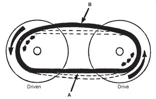
FIG. 7. Fixed sheaves benefit from self-induced torque multiplication. Bombardier
Ltd.

FIG. 8. Series 30 Comet driver assembly for engines developing between 3
and 8 hp. The flyweight and spring assembly (5) cams the moveable flange (8)
toward the fixed flange (12) in response to engine rpm. Go Kart Supply
Operation
Figure 8 illustrates driver assembly for the 30 Series Comet. Pulleys consist of two flanges, one of which is moveable. As the drive-pulley flange moves inward in response to engine rpm, the belt climbs in its groove to increase the effective diameter of the pulley. Since the length of the belt does not change, the spring-loaded flange on the driven pulley opens, reducing its diameter. As one pulley becomes larger, the other pulley must become smaller. The inverse relationship between pulley sizes provides torque multiplication.
Comet transmissions also incorporate a torque-sensing feature. As load increases (say, when climbing a hill), the driven pulley cams are closed, which forces the drive pulley to open for an increase in torque multiplication.
At idle, the belt rides loosely on a brass bushing at the base of the drive sheave. In this position it transmits no torque and generates no friction ( Fig. 9A). As the throttle opens, centrifugal weights cam the pulley's move able flange inward ( Fig. 9B). The belt, squeezed between the moveable and fixed flanges, climbs higher in its groove to increase the effective diameter of the pulley. At the same time, the driven pulley opens, making its diameter smaller. Engine torque is multiplied by a factor of three.
With increased rpm, the belt moves further out on the drive pulley and the driven pulley becomes correspondingly smaller ( Fig. 9C). Pulley diameters equalize. Should load increase, as during acceleration, the engine slows and the transmission downshifts to a lower ratio.
At high speed, the mismatch between pulley diameters sends the transmission into overdrive ( Fig. 9D). That is, the driven pulley turns about 20% faster than the drive pulley to reduce engine wear and fuel consumption.
Troubleshooting
Creep at idle can be caused by a belt that is too short or one that is installed wrong. The asymmetric belt used on 30 Series converters should have its flat side next to the engine. Pulleys need to be in dead alignment.
Check that the springs and pins in the flyweight assembly are tight. Any play in these parts prevents the transmission from disengaging. A worn hub or loss of driven-pulley spring tension has the same effect.
Drive belt malfunctions and their cures are described in Tbl. 4. To that it should be added that the drive pulley includes plastic buttons that limit how far the moveable flange opens. Wear or loss of these buttons allows the underside of the belt to contact rivet heads on the pulley. The resulting wear is rapid.
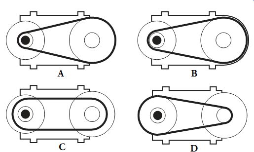
FIG. 9. At idle, the drive pulley opens wide so that the belt rides loosely
between the drive flanges, neither transmitting power nor generating friction
(A). As rpm rises, the moveable flange moves inward, gripping the belt to initiate
power transmission (B). The difference in pulley diameters creates a torque
multiplication of about 3:1. Open the throttle more and the belt rises on the
drive pulley and sinks deeper into driven element (C). Pulley diameters equalize.
At wide-open throttle the drive pulley overdrives its mate, reducing engine
revolutions by about 20% (D).
Go Kart Supply
Erratic engagement is usually caused by sticking flyweights or a binding hub in the drive pulley. Disassemble, clean, and lubricate with a dry molybdenum-based lubricant such as Comet GP-730A. Figure 7-10 indicates lube points. Conventional greases cannot withstand the heat generated by these transmissions.
Tbl. 4 Drive Belt Diagnosis
-----------------
Symptom
Rapid belt wear
Belt worn thin in one spot
Belt cupped (worn concave E on flanks)
Belt disintegrated
Belt "roll over"
Cord breakage on belt edge
Belt worn unevenly P on one side
Belt glazed
Wear concentrated on R the upper edges of the belt
------
Probable Cause
Drive belt installed wrong S Wrong belt
Belt too short Pulley misalignment Malfunctioning drive pulley Overloading-climbing hills, dragging brakes, etc Locked axle Drive pulley malfunction Idle speed too high Excessive run out on R drive pulley
Excessive engine rpm Pulley misalignment Excessive run out on R drive pulley Excessive belt speed Pulley misalignment Pulley misalignment Pulley malfunction allowing C belt to slip Excessive horsepower C for converter Oil on belt, often a residue C of belt manufacturer's mold release
-------
Comments Series 30 torque converters use an asymmetric belt with the flat side toward the engine.
Clean and lubricate drive pulley.
Repair or replace drive pulley.
Align pulleys.
Repair or replace drive pulley.
Reduce engine speed.
Align pulleys.
Align pulleys.
Check drive and driven pulleys.
Contact Kart Supply for support.
Clean belt and pulleys.
Replace belt with correct PN.
----------------------
Adjustments
The tension of the coil spring that holds the moveable flange of the driven pulley against the fixed flange can be varied. The spring anchors in any of three numbered holes. Hole No. 1 provides least tension and early shifting; No. 2 is the factory default setting; and hole No. 3 is for uneven terrain.
The foregoing discussion owes much to Chet Dowden, president of Go Kart Supply (www.gokartsupply.com) and a long-time Comet dealer.
Drive chains
The American Standards Institute (ASI) assigns a two-digit code number to roller chains. The first digit describes the pitch, or the spacing between link centers, in eigths of an inch; second digit is "0" for standard chains. Thus, a No. 40 chain has a pitch of 4/8 or 1/2 inch. A No. 41 is a narrow version of the 40. Metric chains are also sized in inches, but the count is based on six teenths. A No. 8 metric chain is equivalent to an ASI 40.
Alloy steel chains are surprisingly strong. A No. 40 bicycle chain can with stand a ton and a half of force before it elongates and snaps. But for reasonable life, force should be limited to 800 lb or less.
Chains should be cleaned periodically and by soaking in solvent. Most small power transmission chains employ a master link with a removable plate secured by a spring clip. The chain may need to be flexed slightly to free the side plate.
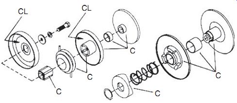
FIG. 10. Series 30 transmission with cleaning (C) and lubrication points
(L).
Go Kart Supply
Like cold remedies, there are many chain lubricants, each claiming superiority. Molybdenum disulfide is an old standby, available in aerosol form where it is mixed with a light oil carrier. Apply MoS2 to the rollers, and when it dries, brush a thick coat of motor oil on the chain to inhibit rust. Castor oil, the original engine lubricant, also makes an effective rust inhibitor. But the type of lubricant is less important than frequent application.
Too much chain tension wears the chain, sprocket, and bearings. Too little tension results in flutter, snatch, and slip (not to be confused with the name of a law office). A 1/4 in. of free play between shaft centers is correct for the sort of applications discussed here. For vehicles with rear suspension, this measurement should be made with the rider aboard. Because suspension pivots rarely share the same center as the drive sprocket, chain tension varies with load.
Chains wear out early because of sprocket misalignment, insufficient tension, and inattention to lubrication. Chains elongate with wear, but do not stretch like taffy. Instead, the pivoting parts-pins, bushings and the rollers that ride on them-develop play, which is cumulative. A chain that has elongated 2% or more should be replaced in order to protect the sprockets from damage. Chains for light motorcycles and motorized bicycles average about 100 1/2-in. links. Moving the rear wheel back 1 in. rep resents the wear limit.
Sprockets
For most applications, the drive sprocket is about a quarter of the diameter of the driven sprocket and, as a result, wears about four times faster. One way to detect sprocket wear is to wrap a new chain over it. There should be some clearance between the chain and teeth, but not enough to be felt when the chain is tugged.
As the chain wears, the pitch increases. Rollers, now spaced too widely for the sprocket, bite down hard on the trailing edges of the teeth. Once past the surface hardening, wear progresses rapidly. The undercut teeth form themselves into hooks that snag on the chain and are quickly ground away.
While there's not much we can do about manufactured equipment, people who design their own gear can extend chain life with a few simple rules.
The most basic of these rules is that the small sprocket should have at least 120° of chain wrap. To say this in a slightly different way, nine teeth in con tact is the minimum, with 15 teeth preferred.
The chain-wrap requirement affects other aspects of the design. To maintain proper tooth contact, the speed ratio should be no more than 6:1 and the distance between sprocket centers should be between 30 and 50 chain pitches. If you are using 41 chain (as strong as 40, but narrower), the center distance should be no less than 15 in. and no more than 25 in.
Geared drives
Gearboxes for portable tools are simple devices that, for the most part, consist of a pair of spur gears riding on antifriction bearings. The information supplied here should more than suffice. Multispeed gearboxes used on light motorcycles and on some racing go-karts are another matter. For these, you need a factory manual.
Disassembly
When the driven component-trimmer head, sprocket, auger bit-rotates clockwise, its fastener nearly always has a left-hand thread. Otherwise, the fastener would work itself loose.
In order to unscrew the nut, the shaft must be prevented from turning.
How this is done varies. Some shafts have flats for wrench purchase, others lock with a punch as shown in ( Fig. 11). Dolmar trimmers/brush cutters set the standard with a push-button stop ( Fig. 12). When all else fails, reach for the air wrench.
Remove all traces of dirt and grease from external surfaces and place the unit on a clean bench for disassembly.
Some output shafts are sealed against dust and water entry. The protective seal may be a separate component or it may incorporate an oil seal on its inner side. The seal will be destroyed during removal; so before you begin, record the number, which should be visible. Also note the shape of the elastomer lip: a seal designed to fend off external threats has the steep side of its lip outboard, away from the gearbox. An oil seal will have its steep side facing inward.
Notches on the unit pictured in Fig. 13 enable the seal to be jimmied out from around the shaft. If the manufacturer has not been so considerate, collapse the seal with a dull punch. Flatten the metal face so that the rim pulls away from the seal boss. Work slowly, exercising care not to score the boss or the shaft.
Snap rings, usually backed by spacers, locate the shafts, the bearings in their bosses, and set the gear mesh. Remove the rings with the appropriate tool that, for deep-seated snap rings, may take some hunting to find (Fig. 14). Lay out the spacers in order of disassembly.
Antifriction bearings are press-fitted into the aluminum case. Gear cases that split along the centerline of the bearing make disassembly easy (Fig. 15).
But if the case encircles the bearing, the interference fit must be overcome.
Loss of interference fit means the bearing has spun. The surest repair is to replace the gear case, but green Loctite 2701 works for moderate over-sizes on the order of 0.003 in.
If the shaft is hollow and accessible from below, a bolt and nut can serve as a puller ( Fig. 16). But the safest, least destructive way to remove bearings is to heat the housing to around 250°F (121°C). For safety, flush the gear case with nonflammable solvent followed by a water rinse. Spray the disassembled parts with WD-40 to prevent rust.
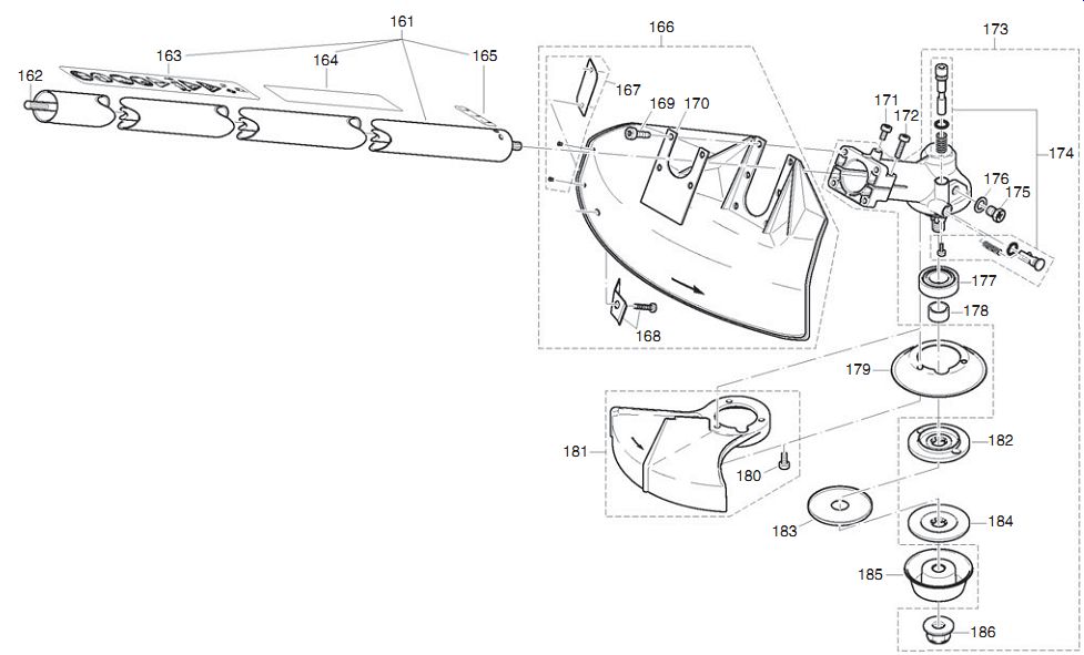
FIG. 11. Dolmar's spring-loaded shaft lock (shown at 174) is a real convenience.
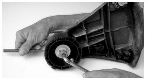
FIG. 12. Most trimmer heads can be locked with a small punch. FIG. 13. Notches
on the side of the case simplify seal removal. FIG. 14. Snap rings and shims
locate shaft assemblies.
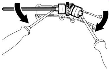
FIG. 15. STIHL angle-drive comes apart easily. A special gear lubricant for
this application is available from factory dealers.
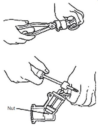
FIG. 16. Bearing pullers can be cob bled together from nuts, washers and
all thread. Vise-Grips, fitted with a slide hammer that replaces the adjustment
screw, comes in handily. Hitachi Koki USA
Unless the bearings will be replaced, leave them attached to the shafts ( Fig. 17). Worn bearings can be driven off with a mallet ( Fig. 18) or freed with moderate heat.
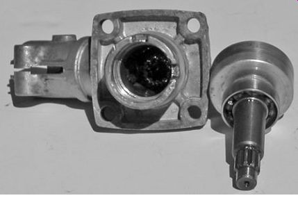
FIG. 17. Unless they are to be replaced, leave the bearings attached to their
shafts.
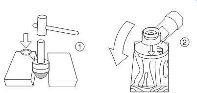
FIG. 18. Old bearings can be driven off their shafts with a soft mallet.
If the bearing remains in the housing, apply heat and rap the housing against
a wood block.
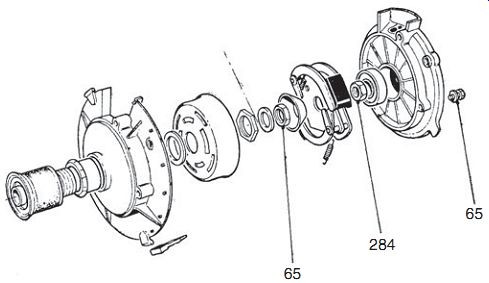
FIG. 19. Velosolex drive in exploded view. Numbers are torque specifications
in in/lb. The engine mounted over the front wheel and turned with it, a configuration
that gave a pendulum-like persistence to the steering. On the other hand, the
mechanicals were well clear of the rider and easy to adapt to bicycle frames.
Homebuilders might reconsider front-wheel friction drive, now that engines
weigh half as much as the old Velo.
Assembly
A light bulb gives off enough heat to expand bearing inner races for a slip fit with their shafts. Note that sealed bearings go on with their closed faces out. Heat the gearbox as before to insert shafts and bearings. As the second shaft is installed, rotate it as necessary to bring the gear teeth into mesh.
Fill the gearbox with the manufacturer's recommended oil. Otherwise, use Mobil-1 75W-90 or an equivalent synthetic gear oil.
Friction drive I could not sign off without mentioning the Velosolex moped. Home builders can learn a great deal from this machine that, more than any automobile, motorized France. Like the Model T, the Velosolex is a study in simplicity ( Fig. 19).
The engine mounted over the front wheel and drove through a friction roller. This arrangement gave the necessary gear reduction in one swoop, without recourse to a jackshaft. A handlebar lever raised and lowered the engine into contact with the wheel, although a centrifugal clutch was included in the package.
Because it's less than positive, friction drive reduces wear on the clutch, which is a perennial problem with homebuilt motorbikes. An automotive suspension bushing makes a suitable roller, although some builders prefer to use stacked disks cut from leather or old tires.
Sign off
We've pretty well covered two-stroke engines, how they work and what to do when something goes wrong. I hope readers find the information useful and in the best sense of the word empowering. And now it's time to get back to the shop.
Prev.
Home Article
index top
of page