Major engine repairs are initiated by weak compression, crankcase leaks, and other obvious signs of distress, such as a scored piston or a rattling connecting rod.
Tests
If an engine develops normal compression and the crankcase holds air pressure, the rod and main bearings are probably okay.
Cylinder compression
Handheld engines should develop at least 90 psi of compression for reliable starting. Utility engines are more tolerant: some can be persuaded to start with as little as 60 psi.
To test compression:
• Shut off the ignition or ground the spark-plug lead to protect the coil (and yourself) from high voltage.
• Make up a compression gauge to the spark-plug port.
• With the throttle and choke wide open, crank the engine through three or four times ( Fig. 1). If compression is lacking, remove the muffler and check the condition of the rings and cylinder as described in Section 2, "Troubleshooting."
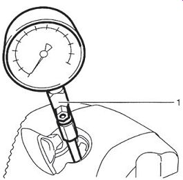
FIG. 1. Small-engine mechanics live by their compression gauges.
Crankcase integrity
Worn shaft seals are the major cause of crankcase compression leaks. To deter mine if a leak is present, we must isolate the crankcase from the atmosphere.
If the cylinder barrel is detachable, replace the barrel with a cover plate. For ease of construction, these plates are usually made of quarter-inch aluminum and sealed with silicone. Drill and tap the plate for a hose fitting and seal off the fuel-pump pulse line, when present. Engines with non-detachable cylinders require two cover plates: one for the intake port and the other for the exhaust. As shown in Fig. 2, the intake-port cover incorporates the hose fitting,
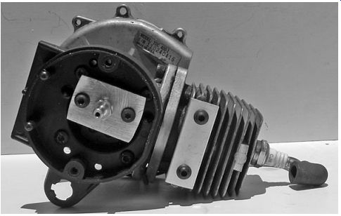
FIG. 2. The crankcase and cylinder for this engine share the same casting,
which means than both the intake and exhaust ports must be sealed.
Vacuum test
A vacuum test replicates conditions during the intake phase, when atmospheric pressure forces seal lips out of contact with the crank shaft. Auto parts stores carry inexpensive hand-operated vacuum pumps, intended for testing emissions hardware. Better quality vacuum pumps can be had from small-engine dealers.
Draw down the crankcase to 7 psi. If pressure remains constant or increases by no more than 4.5 psi over 20 seconds, the seals should be okay.
Pressure test
Careful mechanics double-check the results of the vacuum test by applying positive pressure to the crankcase. This operation requires a 7-psi source of compressed air, which a bicycle pump can provide.
Pressure should hold steady for 20 seconds.
Crankcases may also leak across gasketed surfaces or because of casting defects. To check the whole assembly, pressurize the crankcase to no more than 7 psi, immerse it in solvent, and trace any bubbles back to their sources.
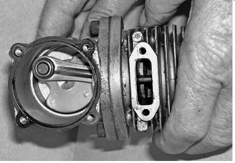
FIG. 3. Cantilevered crankshafts and detachable cylinder barrels simplify
repair.
Overview
Single main-bearing engines that combine the cylinder and crankcase into a common casting come apart easily ( Fig. 3). Vertically split crankcases may be a bit difficult to separate, since the main bearings and alignment pins make interference fits with the casting halves ( Fig. 4).
FIG. 4. Vertically split crankcases are standard ware on light motorcycles and moped engines, such as the Morini shown. The resistance of main-bearing fits, sealant, and locating pins must be overcome without distorting the cases.
Fasteners
Handheld equipment relies upon a mixture of fastener types. Critical components, such as mufflers and cylinder barrels, secure by cap screws, almost always metric. An M8 × 1.0 × 15 screw has a diameter of 8 mm, one thread per millimeter, and a length of 15 mm. The relatively coarse 1-mm pitch is standard for makeup to aluminum.
One also encounters self-threading screws. Shrouding and other plastic parts are secured to plastic with P (Plastoform) screws and to aluminum with DG screws. These specialized fasteners have coarse threads, almost like wood screws, and Phillips, Posi-Drive, or Torx heads.
P and DG screws are not interchangeable and in an ideal world would be installed with a torque wrench. In any event, place the screw in its hole and turn it counterclockwise until it drops down into the existing thread. Failure to feed the screw properly forms a new and weaker thread. It's also important not to interchange binding-head screws (i.e., those with serrations on the underside of the head) with nonbinding screws. Make notes during disassembly and store fasteners and other small parts in labeled sandwich bags.
Tbl. 1 lists ball-park torque limits for fasteners that thread into plastic or aluminum. Those designed "M" are conventional metric cap screws and nuts. Note that torque limits are conservative, intended to protect the threads in base material from stripping.
P and DG torque limits vary with the application. For example, 6-mm diameter P screws generally need about 4.5 ft/lb to generate vibration-resistant clamping force. But the same diameter screw, when threaded into a thin blower hose, is tight enough at 3.0 ft/lb. More torque and the threads would strip. It's also true that highly loaded DG fasteners benefit from more torque than indicated in the table.
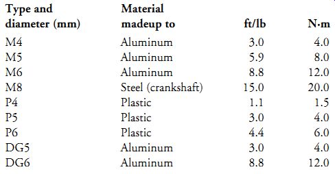
Tbl. 1 Approximate torque values for makeup to plastic or light metal
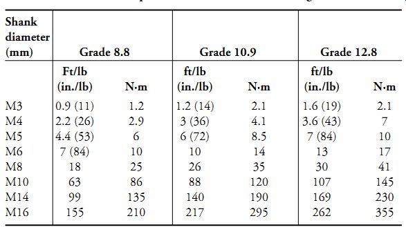
Tbl. 2 Metric torque limits based on fastener strength
Less frequently encountered are fasteners that make up to a nut or into a heavy cast-iron or steel component. For these applications, the strength of the fastener determines the torque limit. As shown in Tbl. 2, metric bolts come in three grades, the weakest being Grade 8.8. Note that 8.8 bolts shear easily, at least for those of us accustomed to inch-standard fasteners.
Torque tables give one a sense of the lay of the ground. For example, it's useful to know that grade 8.8 metric fasteners are only about half as strong as grade 12.8. It's also useful to know that aluminum threads withstand no more three-quarters of the torque of steel threads. (Actually half or two-thirds of steel torque is safer.). But do not be misled by the emphasis on precise numbers.
People who work with machinery develop a sense of how tight is tight enough. Torque wrenches come into play only on critical assemblies, such as flywheels and cylinder barrels.
To avoid strip outs when threading into aluminum or magnesium, lubricate the fastener with motor oil, run in the fastener three full turns by hand, and tighten with a 1/4-in. square-drive ratchet wrench. Larger wrenches invite over-torquing. Draw down fasteners in a criss-cross pattern, working from the center fasteners outward. Torque in at least three increments.
Adhesives and sealants
Critical fasteners, such as those that hold the cylinder to the crankcase, should be secured with a few drops of medium-strength anaerobic adhesive, such as Loctite 242 (blue). Locktite 222MS (purple) is appropriate for 1/4-in. and smaller fasteners. These and equivalent "chemical lock washers" from Omnifit, Prolock, and Hernon develop considerable force as they cure and expand. They should not be used on plastics.
Everyone has a favorite sealant, with RTV (room temperature vulcanizing) silicone a leading contender. However, silicone smears on thick, dissolves in gasoline, and squeezes out with the potential for clogging oil passages. In the writer's opinion, something on the order of Permatex Aviation Form-a-Gasket 80019 is a better choice. This sealant goes on with a brush and withstands temperatures of 400°F (204°C).
Oiling or greasing factory gaskets makes for easy disassembly and, in many cases, allows the gaskets to be reused. But aftermarket gaskets are often made of untreated paper. These gaskets should be doped with Permatex or an equivalent product.
Caution: Remove all gasket and sealant residue prior to assembly. While paint remover can be used to soften old gaskets, the stuff is nasty. Single edged razor blades of the type sold at hardware stores are a better choice.
To avoid gouging the metal, scrape with the blade held perpendicular to the gasket surface.
Crankcase halves often assemble without a gasket, which puts a great deal of responsibility on the sealant. Three Bond Liquid Gasket 1194 is a favorite of the motorcycle fraternity. I've had good luck with Yamabond 5, available from Yamaha dealers.
Philosophy
Basically there are two ways to approach engine work. Pragmatists are con tent to fix whatever is wrong and move on. The perfectionists among us see engines as collections of raw castings, as diamonds in the rough that need polishing, lapping, and caressing to perform as Nicholas Otto intended. Hopefully, both sets of readers will find this section informative.
Housekeeping
Cleaning is a continuous process, carried on as the shrouding, fuel tank, muffler, flywheel, clutch, and other components are removed. Use a nontoxic degreaser and, if possible, perform initial cleaning outdoors. Home mechanics like to use Gunk aerosol, which is a strong alkaline that converts grease and oil to soap in the presence of water. A pressure washer is more appropriate for really dirty tools, such as concrete saws and chipping hammers.
Internal parts should be cleaned with solvent as they come off and cleaned again in fresh solvent before oiling and assembly. The only components assembled dry are electrical gear, tapered shafts (such as used to secure the flywheel), centrifugal clutches, and fasteners treated with Loctite or sealant.
Everything else should be lubricated with two-stroke oil prior to assembly.
Covering the workbench with newspaper will reduce dust contamination. You will also need a supply of paper towels and a hand cleaner such as Go-Jo, although laundry detergent works in a pinch.
A bench vise makes a convenient work stand for engines with extended crankshafts. But supporting a functional engine by fixing its crankshaft in a vise may have unpleasant consequences A gentle nudge can bring the engine to life. Then the problem becomes how shut the thing off, spinning several thousand times a minute around its crankshaft. Vulnerable spark plugs, those that stand proud of surrounding metal and plastic, can be disabled with a hammer. Eventually the engine will stop of its own accord as the tank runs dry.
Nor should engines be operated without their shrouds and air cleaners.
The same holds for the centrifugal clutches used on portable tools and some motorbikes. For many of these applications, the clutch drum remains with the machine after the engine is removed. Starting the engine without the drum in place sends the clutch shoes flying.
Cylinder head
Detachable cylinder heads secure with four cap screws or long studs that thread into the crankcase. Loosen in an X-pattern. Rusted threads can bind the nuts to their studs with the result that the studs unscrew from the crankcase. If this happens, unthread the nut while holding the stud in a soft jawed vise. (A pipe wrench or Vise-Grips leave tool marks that act as stress risers.) Once the nut comes off, clean the threads on both ends of the stud and apply a few drops of red Loctite 272 to the crankcase-side threads. Run the stud back into the crankcase using two head nuts, butted hard against each other, to provide torque for assembly.
Examine the underside of the head for ragged carbon streaks that indicate a combustion leak. Gasket failure may be accompanied by a warped head casting or loose hold-down bolts.
Black or dark brown deposits in the combustion chamber mean that temperatures have been normal. Colors fade with increased heat. Two-stroke oils containing calcium oxide stain the deposits yellow or yellow-orange when temperatures have been excessive.
High temperatures result from
• Air leaks downstream of the carburetor. The carburetor-flange gasket is the most likely culprit. Other sources of air include the head gasket, cylinder-barrel gasket, and crankshaft seals.
• Lean carburetor mixtures.
• Clogged cooling fins.
• Detonation. Check for excessive advance on engines with adjustable timing. Detonation can also be caused by using low-octane fuel or excessive amounts of oil in the premix.
Remove loose carbon from the combustion chamber and piston top with a soft wire wheel. A dull knife or hardwood scraper works for stubborn deposits. Try not to mar the aluminum: nicks and gouges are marks of an amateur. Be especially careful of gasket surfaces.
Occasionally one encounters a combustion chamber that looks as if it had been struck with bird shot. This sort of damage results from disintegrated bearings, usually needles from the small end of the connecting rod.
Inspect the cooling fins for damage. Heavy, chalk-like oxidation should be brushed off, and the head protected from further damage with a very light coat of flat black paint. Some perfectionists go to the trouble of filing off casting flash and other irregularities that obstruct air flow. But do not polish the fins, which benefit from the rough, as-cast finish.
Stripped or badly worn spark-plug threads can be renewed with a Heli Coil insert.
Polishing the roof of the chamber and piston crown yields a small increase in power and makes cleaning easier in the future. The mirror-like finish acts as a thermal barrier to conserve combustion heat. Begin with fine abrasive paper and finish with progressively finer polishing rouge, avail able from large hardware stores. Of course, all traces of the abrasive must be removed before assembly.
Cylinder heads distort in service ( Fig. 5), a condition that can be corrected with an "Armstrong milling machine". Tape a piece of 360-grit wet-or dry abrasive paper to a piece of plate glass or a machine work table. With your hands centered on the casting, move it over the abrasive in Figure-8 pattern.
Oiling the paper results in a smoother finish. The job is done when the entire gasket surface takes on a satiny appearance. The same technique works on warped carburetor flanges.
As a rule, head gaskets should be renewed whenever the head is lifted. However, the copper gaskets fitted to some European engines can be salvaged by annealing, if not too deeply scored. Heat the gasket with a propane torch and quench it in water.
Fiber gaskets sandwiched between steel sheets have a flat and raised side. The flat side goes down, against the cylinder. Fiber gaskets with a ring of light-gauge steel around the combustion chamber install with the wider side of the ring down.
Cylinder heads on some Dolmar chainsaws and European motorbikes incorporate a compression release in the form of a tiny poppet valve. Filling the head cavity with kerosene will show if the valve leaks, a condition usually caused by carbon on the valve stem or, when the valve is remotely actuated, by a sticking Bowden cable.
To install the cylinder head, clean bolt threads with a wire brush to remove all traces of carbon. Torque the head in two or three increments, tightening the fasteners in X-pattern.
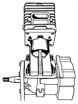
FIG. 6. A slotted wood block prevents the piston from falling against the
crankcase as the cylinder is removed and installed. The vertical plate on the
left of the drawing is a homemade stand for supporting the engine in a vise.
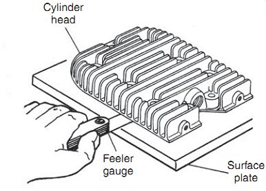
FIG. 5. Measuring head distortion, which on two-cycle engines should be zero
or no more than 0.001 in. You can use a piece of plate glass or a machine work
table in lieu of a surface plate.
Rings and piston
Access to the piston varies with engine design:
• Detachable cylinder barrels, like the one shown back in Fig. 4, lift off once the stud nuts are removed. If the barrel sticks, glancing upward blows with rubber hammer will break the gasket seal.
Cover the crankcase cavity with a shop rag. It is also good practice to support the connecting rod in a suitably slotted wood block as the barrel is lifted ( Fig. 6).
• Fixed cylinder barrels with detachable cylinder heads and two-piece connecting rods require that the piston be pushed out from below ( Fig. 7).
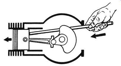
FIG. 7. When the head is detachable and the rod comes apart, drive out the
piston with a hammer handle or wooden dowel.
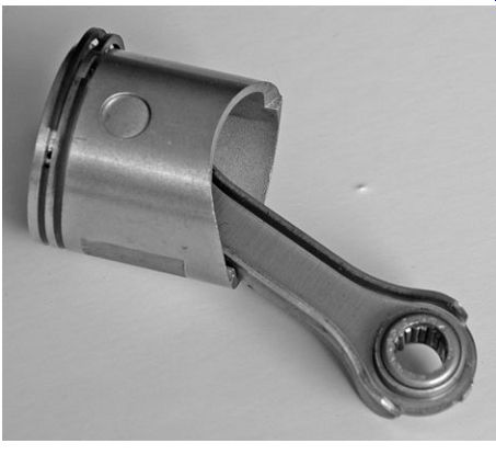
FIG. 8. If rings were free to rotate, the ring ends would snag on the ports.
By looking closely, you can see the locating peg between the ends of the upper
ring.
Rings
Note the orientation of the rings and any features that distinguish one ring from another. Two-stroke rings abut against anti-rotation pegs in the piston grooves. Newer engines often have offset pegs that eliminate confusion during installation ( Fig. 8). Older engines had the top side of each ring marked for correct installation. The marks vary, but it's safe to say that the side of the ring with any inscription on it goes up.
Ring gap
The clearance between the ring ends is important: if too great, some (the exact amount is in dispute) loss of sealing occurs, and if too small, thermal expansion shatters the ring. It's rare to find problems with ring gaps, but careful mechanics verify the gap.
The "Cylinder bore" section that follows describes how the piston is used to push the ring deep into the cylinder and the gap measured with a feeler gauge. High-rpm portable tools require a minimum gap of 0.006 in. per inch of bore diameter. Less stressed engines are set up a few thousandths of an inch tighter. In the absence of factory data, err on the side of generous gaps.
If the gap is too narrow, support the ring in a vise and lightly caress the ends with a fine-toothed file. Try to keep things square and stone the sharp edges left by the file before using the ring. Sharp edges invite fatigue failure.
Ring replacement
Ring expanders for small-bore engines are difficult to come by; most of us manage with a feeler gauge and long-nosed pliers (Figs. 9 and 10). Proceed carefully-rings, especially used rings, are razor sharp.
You may want to detach the piston from the connecting rod, as described below under "Pistons," before cleaning the grooves.
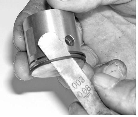
FIG. 9. A feeler gauge can be used like a tire tool to pry rings out of their
grooves.
When installing the lower ring, the gauge acts as a bridge over the upper groove.
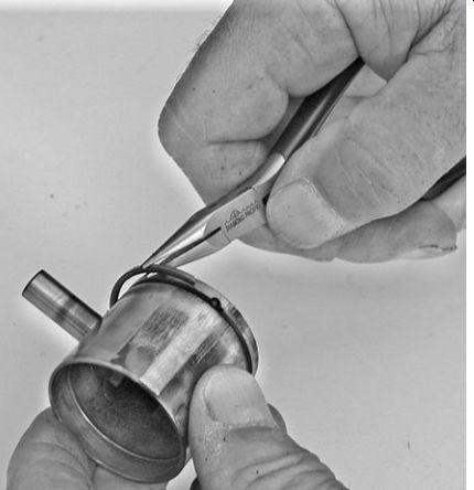
FIG. 10. Long-nosed pliers also help, but be careful not to twist the rings
or stretch them open more than necessary.
Break off one of the old rings square and use it as a scraper. To protect your fingers, mount the ring in a file handle or hold it with Vise-Grips ( Fig. 11).
Do not scrape to virgin metal-a thin veneer of carbon on the base of the groove is more tolerable than loss of metal.
The lower, or No. 2, ring slips over the piston crown, past No. 1 groove, and seats with its ends abutting the groove peg. Be careful not to score the piston with the ring ends. Repeat the operation for No. 1 ring.
Piston installation
Most manufacturers chamfer the lower portion of the cylinder barrel to compress the rings as the piston is inserted. Makers of engines with detach able barrels sometimes furnish their mechanics with a ring compressor, although this tool is more of a convenience than a necessity. Oil the piston and rings liberally with two-stroke lubricant and, if the connecting rod is still on the crankshaft, support the piston as shown back in Fig. 6. The piston and rod slip off of single-bearing, cantilevered cranks, which simplifies things ( Fig. 12)
Carefully lower the barrel over the rings. If it binds, do not force the issue.
Verify that the rings butt against their locating pegs. A hose clamp, loosely tightened over the rings, can serve as a compressor. The cutout on piston ported barrels gives some limited access for ring compression ( Fig. 13).
Once the piston is home, check your work by gently pressing on the rings with a screwdriver from the exhaust port. The rings should flex a few thousandths of an inch and spring back.
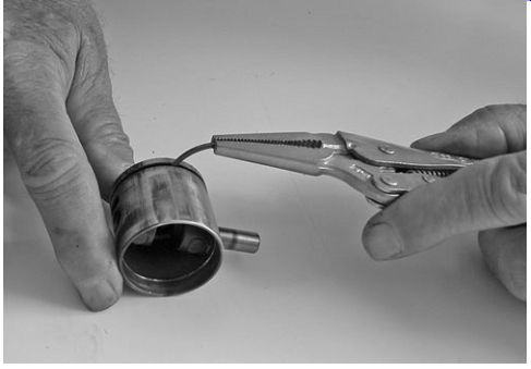
FIG. 11. Cleaning ring grooves prepares the piston to accept new rings.
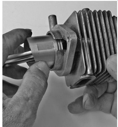
FIG. 12. One of the few advantages of having a single main bearing is that
the rod slips off the crankpin, making piston installation easy. FIG. 13. The
cutaway portion on some cylinder liners can be used to compress the rings before
they meet the bore.
Detachable cylinder barrels, especially those held by only two cap screws, tend to come adrift. Apply a few drops of Loctite to the threads and tighten in three increments, drawing down the screws evenly.
Pistons
With good maintenance, a piston should outwear two sets of rings before replacement. Normal wear polishes the piston skirt to a uniform sheen with out the deep scores, carbon streaks, or weld splotches caused by overheating or loss of lubrication. The piston in Fig. 14 exhibits this sort of damage, as opposed to normal wear. The deep gouge above the ring, probably caused by a flake of carbon, would itself be reason enough to reject the part.
Scores on the upper area of the thrust face point to a lubrication failure, either as the result of massive blowby that scoured the oil film or simply because someone neglected to use the right amount of oil in the premix.
The way the whole skirt is blackened means that combustion gases leaked past the rings. Yet with all that, combustion temperatures were normal as evidenced by black carbon on the piston crown.
FIG. 14. This sort of damage calls for a new piston and cylinder.
Piston removal and installation Snap rings, called circlips in the trade, anchor the wrist pin to the piston. Should a circlip fail, the pin can drift into the cylinder wall with disastrous consequences. Always use new circlips, positioned in the pin bores their open ends on the long cylinder axis. If the cylinder mounts vertically, with the open ends of the clips should be either up or down. Otherwise, the side forces generated at mid-stroke can loosen the clips.
All modern engines support the wrist pin on needle bearings and many have spacers between the piston and rod end. Small-end bearings may be caged, as shown in Fig. 15, or loose. A magnet helps restrain loose needles. When all needles are accounted for, the bearing will be packed without room for another needle.
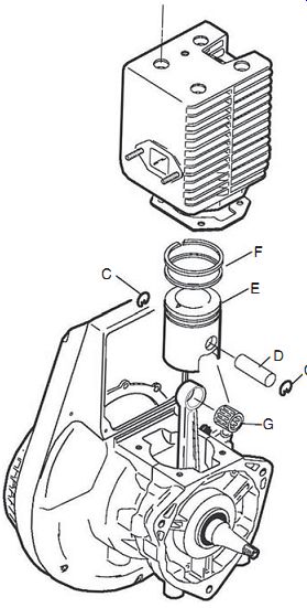
FIG. 15. Wacker Neuson WM80 upper end. The wrist or piston pin (D) rides
on a caged needle bearing (G) and is secured by circlips (C). Note that the
open ends of the circlips point down.
Conventional circlips, also known as internal retaining rings, are removed and installed with snap-ring or long-nosed pliers ( Fig. 16). Constant-section, or hook less, circlips as used on the STIHL 4-Mix, must be pried loose with a scribe. The company makes a clever magnetic tool to aid installation, although a correctly sized punch will work, if you're careful to seat the clip in its groove with the open end up ( Fig. 17).
Warning: Wear safety glasses when working with circlips.
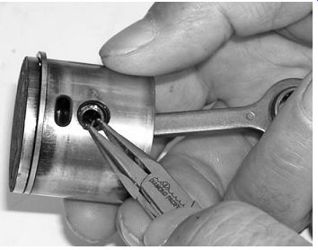
FIG. 16. Circlips with bent tangs are removed and installed with miniature
long nosed pliers. Snap-ring pliers, available from auto supply stores, are
used to remove clips with pierced "ears."
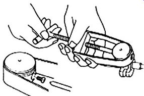
FIG. 18. Tanaka piston-pin extractor. This and other factory tools sometimes
appear on Ebay.
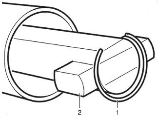
FIG. 17. STIHL's PN 5910 893 1704 employs a magnet (2) to hold the circlip
(1) and a sliding sleeve to force it home.
Once the circlips have been removed, the pin can be driven out with a flat punch or, better, pressed out with the appropriate tool ( Fig. 18). If you use a punch, be extremely careful not to score the piston-pin boss.
After detaching the piston, turn the flywheel to bring the rod to top dead center (TDC) and using Fig. 19 as a reference:
• Slide the wrist pin back and forth in its rod bearing. The pin should move easily.
• Attempt to move the pin up and down. If the bearing is good, movement will verge on the imperceptible.
• Try to tilt the wrist pin in its bearing. If there is more than a few thousandths of an inch of play, the needles are tapered and should be replaced.
• Repeat these tests on the big-end bearing. The rod should slide easily along the crankpin, but should exhibit no more than 0.001 or 0.002 in. of up-and-down movement. Movement should be felt as a single phenomenon; if you feel the rod accelerate and halt as you pull on it, bearing clearances are too great.
• And finally, tilt rod on the big-end bearing as was done with the wrist pin and its bearing. If the upper end of the conn rod arcs an eighth inch or more, the rollers have worn conical-that is, they are thicker in the middle than on the ends. Tapered big-end bearings create side forces that can drive the wrist pin into the cylinder wall. And finally, note that the eighth-inch-tilt specification is arbitrary. Less is better ( Fig. 19). Rod straightness comes into question when the piston skirt exhibits curved, rather than linear, wear patterns. Figure 20 shows the setup, with a pair of machinist's blocks on the crankcase flange and a new wrist pin as reference. Compensate for crankcase distortion by switching the blocks from one side of the case to the other. Homemade bending bars are used to straighten the rod ( Fig. 21). (Tooth marks left by pliers and pipe wrenches are fatal to conn rods and other highly stressed parts.) Thoroughly lubricate the pin and its bearings with two-stroke oil before assembly.
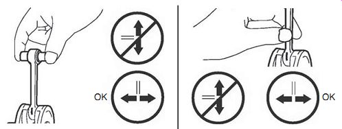
FIG.
19. An experienced mechanic can evaluate bearing condition by feel.
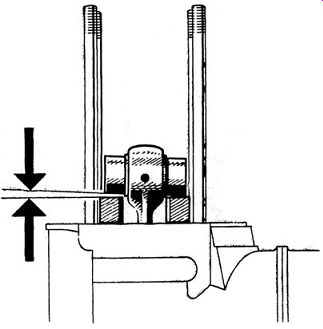
FIG. 20. Check rod trueness with machinist's blocks and a new wrist pin.
Unless one end of the wrist pin is capped and the other end open, the direction of installation is unimportant. However, respect for bedded-in surfaces means that used parts should be assembled as originally found.
Pistons for high-performance engines generally have an arrow or other reference mark that, upon correct assembly, points to the exhaust port (Fig. 22). Pistons without such a mark assemble with the cutaway portion of the skirt adjacent to the intake port. Deflector-type pistons have the steep side of the deflector facing the transfer port. Most loop-scavenged engines have offset rods; reversing the orientation of the piston results in noise and accelerated wear. Doing the same for deflector-type pistons dramatically reduces power.
Shop manuals prescribe that the wrist pin be installed first, followed by the circlips. Most of us find it easier to install the outboard circlip, press the wrist pin into light contact with it, and install the remaining clip.
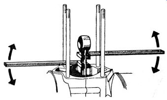
FIG. 21. The lower bar goes just under the bend and the upper bar applies
the corrective force. Steyr-Diamler-Puch
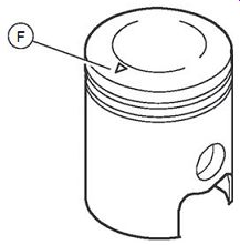
FIG. 22. The arrow on this Wacker Neuson piston crown points to the exhaust
port.
Cylinder bores
Wipe the bore with a clean shop towel. Severe damage is obvious to the eye, although touch is a far better guide to surface finish. Fingertips can detect irregularities as small as 1 µm (1/25,000 of an inch), or about 100 times smaller than those we can see. Cylinder wear appears as:
• Discoloration that signals loss of ring contact-caused by overheating and distortion.
• Deep grooves along the length of the bore-caused by carbon flakes or broken rings. Replace or, when practical, machine the cylinder oversized.
• Scratches around the exhaust port- if local, these scratches can be tolerated.
• Fine, almost invisible scratches that have the feel of a cat's tongue- caused by abrasive damage. Replace or rebore the cylinder, followed by repairs to the air cleaner or intake gasket.
• Peeled or worn-through chrome or Nikasil coatings on aluminum bores-replace the cylinder.
• Aluminum splatter-chrome-plated and cast-iron bores can be cleaned up with muriatic acid. Flush with water and oil the bore immediately to prevent rust. The underlying cooling and/or lubrication problem must be identified and corrected.
Permissible limits to bore wear and distortion are less rigid than one might suppose. Barring accident, the bore should outlast two pistons or four ring sets. When wear limits are provided, few shops have the precision instrumentation needed to apply them. Most mechanics judge wear by how much the piston wobbles.
Unlike bearing wear that, if allowed to accumulate, results in catastrophic failure, bore wear is relatively benign. Engines with excessive bore wear usually refuse to start before they hurt themselves.
But any deviation from perfectly round and straight cylinders costs power. A few ten-thousandths of an inch can make the difference between winning and losing racing engines. At the other extreme, slow-turning utility engines merely need enough compression to crank. Some of these thumpers run for years with 0.005 in. and more of bore wear.
High-revving portable tools are a special case. Two-inch bores and six figure rpm put a premium upon precision, especially when Nikasil coatings are involved. For example, the 43-mm bore of Tanaka TBC-600 trimmer has a wear limit of 0.04 mm, or 0.0016 in.
The easiest way to determine bore wear is to measure the cylinder with direct-reading cylinder-bore gauge. To be able to trust the readings, one must invest in a quality Japanese or American tool with a history of recent calibration. Few shops have tools of such precision. Telescoping gauges for use with a micrometer are a less expensive alternative, but require almost superhuman skill to read when dimensions are expressed in tens of thousandths of an inch.
The poor man's approach is to measure wear as ring gap. Using the piston as a pilot, insert the ring deep into the bore in the area that experiences least wear. Measure the gap with a feeler gauge. Repeat the measurement with the ring positioned just below TDC. The difference is, roughly speaking, the amount of cylinder wear.
Old iron
Cast-iron was the wonder metal of the industrial age: inexpensive, easy to pour and machine, and unique in the way it could run against itself without protest. Iron cylinders and cast-iron rings are fully compatible.
Classic engines, such as the Harley-Davidson Knucklehead and Volkswagen air-cooled fours had gray cast-iron cylinders that produce a dull thud when struck with a ball-peen hammer. This is the sound of good vibration dampening.
Unfortunately, the Chinese iron generally available today is not of this quality and lacks homogeneity. It expands unevenly when heated and may crack. If an iron barrel "pings" when struck, it's made of inferior stuff.
But even the best iron is heavy and, relative to aluminum, is a very poor conductor of heat. As a compromise, many utility engines and motorbikes employ aluminum cylinders and thin-walled iron liners, or sleeves.
American engines have non-renewable liners, cast integrally with the aluminum "muff." European and some Asian manufacturers machine the cylinder barrel to accept a liner, which is then pressed into place. These liners can be renewed when worn.
The presence of an iron liner can be verified with a magnet, although the ends of the liner are usually quite visible as a ring, about 3-mm thick, around the bore.
Honing
Several makers of automotive piston rings have questioned the utility of "glaze breaking," but small-engine mechanics always hone iron liners when new rings are installed. Honing removes small imperfections and roughens the metal to speed the wearing-in process. Chrome rings benefit most.
The tool of choice is a Flex-Hone, a brush with abrasive balls on the end of its bristles and sized 10% smaller than the cylinder bore. Adjustable hones are available for 2-in. and larger bores. Medium-grid (No. 220 or 280) aluminum-oxide stones are appropriate for the chrome-plated rings nearly always used on these engines. Home mechanics may have to use a brake cylinder hone, which is better than nothing.
Mount the hone in a drill press or low-speed portable drill, lubricate the cylinder with the proper honing oil, and run the hone up and down in the bore. Adjust the reciprocating speed to produce a 45° to 30° cross-hatch pattern. Keep the hone moving, pausing at the ends of the stroke only long enough to reverse direction. Stop when the cylinder takes on a uniform appearance, a condition that occurs more consistently with a Flex-Hone. Removing the last patches of glaze with an adjustable hone costs more metal than it's worth.
Finish with a mild abrasive such as a Scotch-Brite pad or a piece of No. 600 wet-or-dry paper taped to the hone. A few strokes is all that's necessary to flatten, or "plateau," the peaks left by the hone. This operation also releases some of the entrapped abrasive that would play havoc with rings.
But abrasive fragments remain. Scrub the bore with water as hot as you can stand and a strong detergent. Some mechanics favor Tide; others swear by Lava hand soap. Continue to scrub, wiping the bore with paper towels until there is no trace of discoloration. As a final tribute to the persistence of aluminum oxide and to the propensity of iron to rust, scrub the bore with automatic transmission fluid. Chamfer the sharp edges of the cylinder ports with a small stone.
Worn liners can be bored oversize or replaced. But this work requires specialized tools and expertise.
Aluminum bores
Aluminum bores run cooler than iron and, of course, weighs less. And since an aluminum cylinder expands at nearly the same rate as the piston, running clearances can be reduced. But, unlike cast iron, aluminum scuffs when run against itself. If the engine is to live, cylinder bores must be armored with one or another type of coating. The bores of most quality two-stroke engines are coated with a thin veneer of chromium, applied by an electro-diffusion process that leaves microscopic voids for oil retention. Example include some of the better motorcycles, outboard motors and handheld tools, such as Husky, Elco, Shindaiwa and the Poulan "yellow" series. Low-end manufacturers merely chrome the piston, which then runs against the raw aluminum bore. A chromed piston leaves the cylinder bore at the mercy of the rings.
In 1967 Mahle developed a super-hard coating to combat wear in the Wankel rotary engine. Marketed under the name Nikasil, the coating consists of microscopic silicon-carbide particles imbedded in a nickel matrix. As the nickel wears, carbide becomes the bearing surface. Nikasil is harder than chrome, less liable to peel, and withstands temperatures of 1200°F (648°C).
It also dissipates heat better than chrome, and closely mimics piston expansion so that skirt/bore clearances can be almost nil. When the cross-hatching is no longer visible, a Nikasil cylinder has worn past tolerance. Another advantage is that piston rings seal with very little tension, which results in less friction, less heat, and more power.
Nikasil has drawbacks, not the least of which is the cost. Thickness after factory honing can be as little as 0.0015 in., which gives zero protection against the sharp edges of broken rings or ingested solids.
Applications range from Corvette Z-1's and Porche Turbos to quality handheld tools, a category that includes Solo, STIHL, Wacker Neuson, Marurama, Jonsered, and certain Echo products.
Some mechanics attempt to hone Nikasil cylinders when rings are replaced. But, unless they use diamond abrasives, the operation is fruitless.
BMW, for one, cautions against honing.
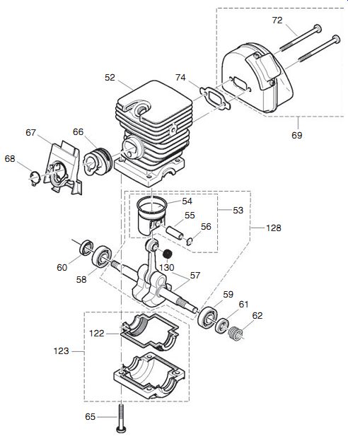
FIG. 23. This Dolmar horizontally split crankcase gives easy access to engine
internals.
Standard practice is to replace worn cylinders, although U.S. Chrome, Millennium Technologies, and a handful of other companies have the technology necessary to refurbish Nikasil cylinders. But the service is not cheap.
Lower end
The lower end consists of the crankshaft, crankshaft seals, bearings, and, if non-detachable, the connecting rod. Gaining access to these parts is easy when the crankshaft cantilevers off a single main bearing. Nor is the work difficult if the crankcases split horizontally at the main bearings ( Fig. 23).
But vertically split crankcases complicate things.
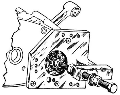
FIG. 24. Joe Bolger, a six-time National New England Motocross Champion,
devised this tool for separating Honda cases. Similar tools can be fabricated
for other engines.
Vertically split crankcases
Crankcases that split in two vertical slices-each of which holds a main bearing and, for motorcycles, half of the transmission-shaft bearings-pose obstacles to separation:
• A special tool, in the form of a metric-threaded hub puller, is often required to extract motorcycle clutches. Equivalent tools can some times be found at bicycle shops.
• Phillips-head screws used by Oriental manufacturers can be difficult to remove even with a hammer-impact driver. If the heads strip, the screws must be drilled out with possible repercussions for the case.
Once they're extracted, replace these screws with Torx or Allen screws.
• The adhesive bond formed by the gasket and/or sealant must be over come, together with bearing and locating-pin fits. There are at least three ways to do this:
1. With luck, a few sharp blows on the crankshaft stub are enough.
2. The least destructive way of overcoming bearing fits, and the way recommended by BMW, is to heat the bearing housing with a propane torch. Keep the flame moving in a circular pattern and stop when the case begins to smoke. Overheating warps the casting and destroys any oil seals that may be present.
3. Another approach is to press out the shaft with a tool that bolts to the crankcase ( Fig. 24).
4. The locating pins in weather-beaten motors sometimes corrode, resulting in local sticking that cannot be overcome with heat.
Typically the cases separate a fraction of an inch and bind. Soak the pins in penetrating oil and wait a few days for the oil to take effect. If that doesn't work, we have to do something radical. While shop manuals warn against prying cases apart, gentle pressure with large screwdrivers will not necessarily score the gasket surfaces.
"Gentle" is the operative word. Work very, very slowly. As the castings separate, keep the gap even. Once apart, replace the pins with new ones.
Inspect the bearing bosses: longitudinal scores reflect the violence of disassembly and can be lived with. Radial scores left by spun bearings require attention. Most mechanics reject such cases, which is tantamount to scrap ping the engine. But when the damage is confined to a single spun bearing, the bearing can be secured with Loctite 271 Stud "N" Bearing Fit. Clean the parts to remove all traces of lubricant and apply the adhesive to both parts.
The resulting bond requires 16 to 36 N.m torque to shear.
When a gasket was fitted between the casing halves, replace it with a factory part of the correct thickness. Otherwise, bearing "float" will be affected. If no gasket was used, coat the mating faces with Yamabond 5 or an equivalent product.
Crankshaft seals
Replace seals that fail to hold vacuum and/or pressure, and as insurance whenever the crankcase is opened. Stand-alone seals are a mark of quality ( Fig. 25). Lesser products employ sealed bearings, which compromise reliability and make what would otherwise be a simple repair an exercise in bearing extraction.
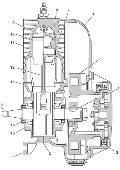
FIG. 25. Wacker Neuson cut-off saw engine in cross section. The stand-alone
seals (15) can be renewed without disturbing the bearings.
Stand-alone seals
These seals lift out with the crankshaft when the crankcases split horizontally. On other engines, the seals remain in the castings as the crankshaft is withdrawn. Note how deeply the seal is installed. Most are flush or slightly under-flush with the surrounding metal. If the seal cannot be driven out from behind, use a small, blunted chisel, crush the seal inward to break its hold on the casting. Work slowly and carefully, a slip of the chisel can ruin your day. Once the seal is loosened, pry it out with a screwdriver.
The same technique works for engines with their seals accessible from outside of the crankcases with the crankshaft in place. Of course, the presence of the crankshaft complicates things, but with patience one can work around the obstruction. Factory mechanics have access to seal pullers that simplify the job.
Examine the crankshaft for scoring. Some crankcases have deep bosses that permit the seals to be repositioned against an unworn portion of the crankshaft. Polish the contact area with fine wet-or-dry abrasive paper.
Oil seals usually have a flexible coating on their rims to prevent leaks around the seal OD. Plain steel rims should be leak-proofed with a light coat of Permatex Aviation sealant prior to installation. Wipe off any sealant that finds its way to the seal lips.
New seals drive or press into place. The numbered side of the seal goes outboard, toward the installation tool. As a further check, examine the elastomer seal lip, which should have its steep side inward, toward crankcase pressure. On some applications, the seal will have a second lip to prevent ingress from outside of the crankcase. If the crankshaft is still in place, that is, if you are installing a seal over the crankshaft, cover the threads and key ways with a single layer of Scotch tape. Otherwise, the seal lips may be damaged.
The driver should have an OD of slightly less than the seal boss and an ID that concentrates installation force on the seal rim ( Fig. 26). Automotive tool suppliers can furnish seal drivers in inch and metric sizes, but these tools come in sets and are expensive. A hardwood dowel, with its end cut square, makes a pretty good substitute. Lubricate the seal lips with grease and install the seal to its original depth.
Crankshaft bearings
Most crankshafts run on ball bearings with internal races that protect the shaft from direct contact with the balls. Rod-bearing needles run directly on the crankpin.
Many manufacturers do not offer option of replacing lower-end bearings- when bearings fail, one either scraps the engine or purchases a short block.
The discussion that follows is limited to those engines for which replacement parts are available.
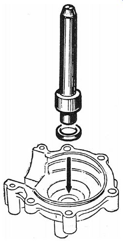
FIG. 26. A hardwood dowel can be substituted for the factory driver shown
here.
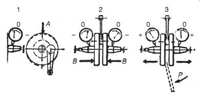
FIG. 27. Shaft misalignments and their cures. If one stub shaft is high,
drive its fly wheel down with a brass hammer (A). If both shafts are low, squeeze
the wheels together (B). And if both shafts are high, pry or wedge the wheels
apart.
Connecting-rod bearings
Vintage two-strokes ran their connecting rods on plain bearings. Once in motion, the rods floated on a cushion of oil, which sounds nice. But keeping the rods afloat required oil/fuel mixtures of 16 or even 12:1. Engines smoked like mosquito foggers.
Because needle bearings make rolling contact with their journals, they need very little lubrication. A 50:1 gasoline-oil mixture is plenty and some engines survive on 100:1. Rolling contact also has drawbacks. Any imperfection-a fatigue flake, a skid mark, or a microscopic rust pit- results in rapid failure.
Full-circle rods
One-piece rods save weight, at the price of complicating repairs on engines with two main bearings. Access to the crankpin bearing requires disassembly of the crankshaft. While anyone with a 15-ton arbor press can disassemble a built-up crankshaft, putting one back into alignment is an exacting process. Figure 27 outlines the procedure, which is easier to write about than do.
Two-piece rods
Tecumseh utility engines and some outboards come with two-piece rods, as shown in Fig. 28. Split races protect the aluminum rod from contact with the needles that, for reasons that are not clear, may be arranged in single or double rows. Match marks on the rod and cap must be aligned for correct assembly and rod bolts torqued to specification.
Main bearings
Evaluating the condition of antifriction bearings involves more art than science. The first step is to remove every trace of oil from the bearing. Allow time for the bearing to air dry and turn it by hand. Any roughness or binding means that the bearing verges on failure. If you have access to a new bearing, use it as a touchstone to determine how much radial and axial play is permissible. A sign of doom is an outer race that slips off the balls.
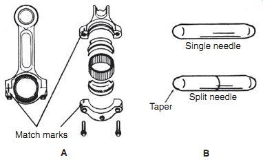
FIG. 28. Two-piece connecting rods with big-end needles are standard on Tecumseh
utility and outboard engines. Note that rod and cap match marks must be aligned
(A) and that needles should pack solidly around the crankpin. If there's space
for another needle, you have lost one. The squared-off ends of split needles
face each other (B). Grease or beeswax can be used to hold the needles in place
during assembly.
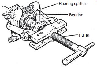
FIG. 29. A bearing splitter extracts some, but not all, main bearings.
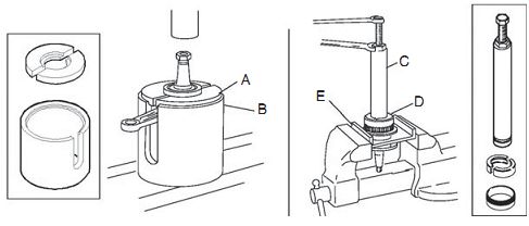
FIG. 30. One of the nice things about quality products is the thought that
goes into special tools. To remove a Wacker Neuson main bearing, mount the
crankshaft in the PN 0023339 support tube (B) and position the PN 0023338 split
ring puller (A) against the bearing. Puller halves may need to be taped into
place. The bearing is then pressed out. As shown on the right, Wacker Neuson
also supplies tools-the PN 0013288 extractor (C), the PN 0017328 half shell
(D), and the PN 0013290 holding ring (E)-that enable bearings to be extracted
without an arbor press.
Caution: Do not spin bearings with compressed air. While gyroscopic progression is an interesting phenomenon, damage to the bearing inevitably occurs.
Figure 29 shows how a bearing splitter and gear puller collaborate to remove a main bearing. When space restrictions prohibit the use of a splitter, factory tooling (or some facsimile of it) must be used ( Fig. 30).
The installation setup for Wacker Neuson engines can be used as a model for others ( Fig. 31). The pusher tube (F) bears against the inner race and the crank support plate isolates the crankpin from bending forces. New bearings go on with their marked sides toward the pusher tube.
Another way to install bearings is to create a heat differential between the shaft and the bearing. Since the interference fit on is on the order of 0.001 in., a differential of 150°F (65.6°C) allows "palm-push" assembly. A light bulb placed against the inner race provides sufficient heat, although one must be careful not to exceed 250°F (121°C), the temperature at which that bearing steel becomes reactive. The bearing can also be heated in oil. If you use this approach, support the bearing above the bottom of the container on wire mesh and work outdoors. Carefully monitor oil temperature.
Now that the hard part is done
Once you have the engine back together, check for any "extra" parts on the bench. Verify that the crankshaft turns easily without hard spots or binds.
Fill the tank-without adding extra "break-in" oil to the premix-and examine the fuel lines and carburetor for leaks.
Pull the starter cord through a few times. Resistance should increase at mid-stroke and peak as the piston rounds top dead center. Engage the choke and give the cord a vigorous pull. Do not be dismayed if the engine does not immediately start. The problem is almost surely an oil-fouled spark plug. Once the engine comes to life, it will smoke a bit until the oil used during assembly burns off. Run at less than full throttle and under moderate, but varying, loads for the first few tanks of fuel. Stop periodically to allow the engine to cool.
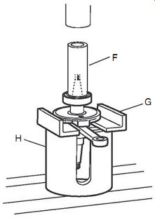
FIG. 31. Bearing installation using Wacker Neuson tooling. Note that the
nearside crank shaft web must be supported.
Prev. | Next
Home Article
index top
of page