Rewind starters, also known as recoil or retractable starters, can be intimidating, especially when the main spring gets loose and beats you about the head and shoulders. Nor are factory manuals, most of them anyway, of much help.
After considerable thought, I have arranged this section into four sections. The Troubleshooting section gives you an idea of things that usually go wrong. The Overview is just that, a way to become familiar with the lay of the ground. Then there are two types of starters, depending upon the engagement mechanism. Clutched starters are the most complicated and least intuitive. The Eaton and a common Japanese starter of unknown manufacture are in this category, and are discussed in some detail. The information provided should enable readers to repair any of these clutched devices. Ratchet starters which work like ratchet wrenches, are the second basic category. You will find these starters on Craftsmen and other inexpensive equipment, as well as on the sublimely professional Wacker Neuson WM 80.
Troubleshooting
Repairs go more smoothly when you have an idea of what to look for.
• Sluggish action
If the starter rope becomes stiff and retracts slowly, assume dirt is the problem. Cold weather that coagulates the grease on the main spring has a similar effect, as does misalignment of the starter with the flywheel cup.
• Broken cord
The cord or rope is usually the first part to fail, especially on hard-starting engines that aggravate their operators. Worn rope ferrules contribute to the problem.
• Failure of the cord to retract If the whole length of the cord extends out of the housing, the main spring has either broken or lost its anchor. Partial retraction usually comes about because of a weak spring. Increasing the pretension on the spring sometimes helps, although the surest cure is to replace the spring. Severe starter/flywheel misalignment will also leave the rope dangling.
• Failure to engage the flywheel
On clutch-type starters, expect to find a loose clutch retainer screw, a worn or distorted brake spring, or oil on the friction surfaces. Ratchet starters fail to engage because of bro ken or twisted ratchet springs or rounded-off ratchet tips. These matters are discussed in more detail later.
• Noise from the starter as the engine runs
Check starter/flywheel alignment.
Overview
Rewind starters share common features. What is learned by repairing one starter applies, with some reservations, to all. That's the good news. The bad news is that rewind starters contain a spring that, should it escape from its housing, becomes a five-foot-long flail. Wear eye protection and gloves when servicing these units.
Disarming
Before dismantling a starter, the main spring must be allowed to uncoil as much as the housing permits. It will still contain energy. Disarming is accomplished either by detaching the cord handle or by partially disengaging the rope from the sheave.
The handle can be removed by untying the knot or by cutting the cord.
Then, using your thumbs as a brake, allow the sheave to unwind. Count the number of turns it makes to be able to apply the same preload upon assembly.
Most sheaves are notched on their outboard sides so that preload can be dissipated with the handle in place. Figure 1 illustrates the procedure.
Turn the sheave counterclockwise to bring the notch in line with the rope ferrule. Lift the cord out of the notch and allow the sheave to unwind in a controlled fashion. Be sure to count the number of revolutions the sheave makes.
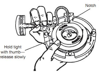
FIG. 1. A notched sheave enables preload to be dissipated with the rope handle
attached. Disengaging a few inches of cord from the sheave increases its effective
length. The sheave then can unwind with the handle attached.
Sheave
The sheave, also known as pulley or rotor, is secured by a central screw or by tabs around its rim. Once the hold-downs are removed, the sheave lifts off to expose the main spring. The trick is to lift the sheave without dislodging the spring from its housing. Should this happen, the unconfined spring lashes about uncontrollably, and you will then be faced with the chore of rewinding it.
The inner, or moveable, end of the spring mates with a slot on the under side of the sheave. Slowly turn the sheave to and fro as if tuning a radio.
When you no longer feel spring tension, the spring no longer drags against the sheave slot and should remain in its housing as the sheave is lifted off.
Carefully raise the sheave: if resistance is felt, stop and start over. I want to warn you again of the importance of wearing safety glasses and gloves when performing operations like this one that can unleash the main spring.
Although one or two manufacturers disagree, sheave bushings need some tiny amount of lubrication.
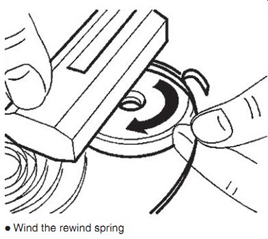
FIG. 2. STIHL main spring installation tool (PN 1116 893 4800). The spring
winds clockwise into the drum, from the outside inward.
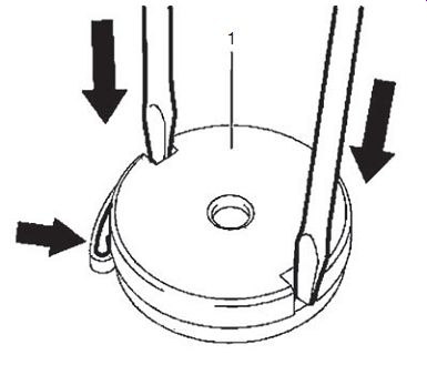
FIG. 3. The spring installs with the assembly block (1) positioned so that
the spring loop is captured by the recess in the housing. Once the spring is
home, the assembly block is removed. ANDREAS STIHL AG & Co. KG
Main spring
Replace the spring if broken, distorted, or too weak to retract the cord.
Otherwise, leave it undisturbed. Replacement springs usually are pre wound. Some come housed in a retainer and install as an assembly. Others are secured by a wire clip, reminiscent of the loading clips used on the old M-1 rifle. Align the outboard spring end with the housing anchor and press the spring out of the clip, which is then discarded. STIHL provides dealer mechanics with a tool for rewinding the spring (Figs.2 and 3). A similar tool-the "EZ Coil Spring Winder"--can be purchased from Week Distributors (telephone: 800/380 3752).
Whether you use a winding tool or install the spring by hand, it is critically important to orient the spring relative to the direction of engine rotation. The spring must wind tighter as the cord is extended. Since the normal direction of rotation of nearly all small engines is clockwise, the lay of the rewind spring is counterclockwise. That is, if you trace the curvature of the spring from its outer coil inward, your finger will move in a counter clockwise spiral.
For cold weather operation lightly grease the spring with Molykote PG 54; springs in dusty environments do better with light oil such as WD-40.
Starter cord The replacement starter cord, or rope, should have the same diameter, length, and weave as the original and it should be made of unalloyed nylon.
If the length is unknown, secure the cord to the sheave and wind until the spring coil binds. Allow the sheave to unwind for one or two turns and cut the rope, leaving enough for handle attachment.
Purchasing cord by the engine maker's part number should obviate problems with material. But shops that buy in bulk should be aware that "nylon" cord may contain polyester fiber. This material has only a third of the strength of nylon and wears quickly. To test for polyester, place a sample of the cord in boiling water and add Rit Dye. Nylon will not absorb color, poly ester will.
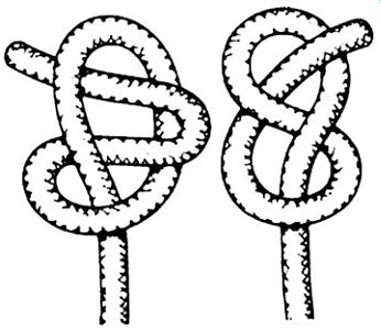
FIG. 4. Nonslip knots are insurance against callbacks. ANDREAS STIHL AG & Co.
KG
In order to prevent fraying and assist in threading the cord through the ferrule, heat the cut end until it flames. Wipe down the hot area with a rag, tapering the end into a point.
Warning: Allow plenty of time for the cord to cool before touching it.
Nylon has almost zero thermal conductivity.
Either of two types of knot can be used ( Fig. 4) to secure the cord to the handle and sheave. Trim the cord close to the knot and cauterize.
Preload
Preload, or the spring tension necessary to fully retract the cord, can be achieved in either of two ways.
Without the cord handle attached:
1. Secure one end of the cord to the sheave. Some manufacturers provide an anchor, others rely upon a nonslip knot.
2. Wind the cord completely over the sheave so that the sheave will turn the flywheel in the normal direction of engine rotation.
3. Install the sheave, anchoring it to the spring.
4. Wind the sheave against the direction of engine rotation the specified number of turns. If the specification is unknown, wind until the spring binds solid and allow the sheave to unwind for one or two revolutions.
5. Hold the sheave against spring tension with C-clamps or Vise Grips. Now thread the cord through the guide ferrule (also called the rope bushing or eyelet) in the starter housing.
6. Attach the handle.
7. Gently pull the starter through to make certain the cord extends to its full length before the onset of coil bind. Verify that the cord retracts smartly.
With handle attached:
1. Assemble the sheave over the spring.
2. Rotate the sheave, winding the mainspring to coil bind.
3. Release spring tension by one or two sheave revolutions.
4. Block the sheave with C-clamps or Vise-Grips to hold spring tension.
5. With the handle attached, thread the cord through the ferrule in the housing and anchor its free end to the sheave.
6. Release the sheave block and, using your thumbs for a brake, allow the sheave to unwind and wrap the cord around itself.
7. Test starter operation.
Note that the first method must be used when the cord anchors to the underside of the sheave.
Clutch-type starters
These starters evolved from the Jacobsen starter of 1928 that drove through a friction clutch. The clutch housing contains ramps that cam one or more pawls (also called dogs) into engagement with the flywheel. While the housing turns with the sheave, the coupling is less than positive. A friction-inducing spring slows the rotation of the clutch housing relative to the sheave. One end of the spring bears against the housing and the other end against the central hold-down screw or other stationary element. Slowing the rotation of the clutch housing has the same effect as reversing its rotation. The pawls cam into engagement with the flywheel cup.
These starters can be recognized by the coil or hairpin friction spring that bears against the clutch body. American starters may employ a star washer.
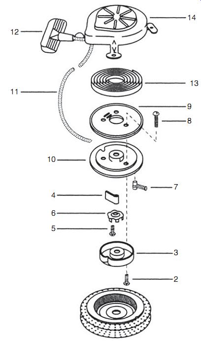
FIG. 5. Eaton light-duty starter of the type frequently specified for Tecumseh
two-strokes.
This starter is distinguished by a star-shaped brake washer (6) and a two-piece sheave (9 and 10). The main spring (13) installs with the aid of a disposable retainer clip.
Eaton
Eaton starters are standard on American utility and trolling motors. Light-duty models have a single engagement pawl ( Fig. 5); heavier-duty models use two and sometimes three pawls ( Fig. 6). Most have a centering pin that rides in a nylon bushing.
Disassembly
1. Remove the screws securing the starter assembly to the blower housing.
2. Release spring preload. Most sheaves are grooved to allow this operation to be done without detaching the handle.
3. Remove the retainer screw and any washers that might be present.
4. Carefully lift off the sheave while keeping the main spring confined within its housing.
Warning: Wear safety glasses and gloves during this and subsequent operations.
5. Remove the cord. A hammer-impact tool may be necessary to undo the fasteners on split sheaves.
6. Springs without retainer cups must be unwound a coil at a time from the center out.
7. Clean parts with nonflammable solvent.
FIG. 6. A slightly more sophisticated Eaton with a single-piece sheave, an optional two-dog clutch (shown on the left), and a cartridge-type main spring and retainer (9). Lock tabs on the retainer OD mean that the spring and retainer remain together as an assembly. Note the absence of a star washer.
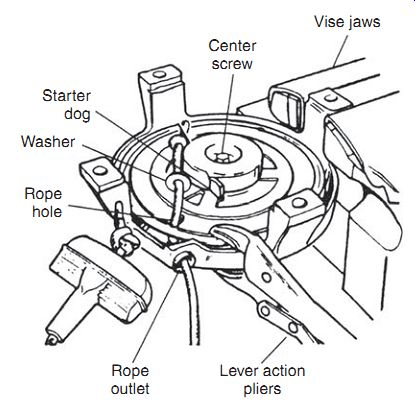
FIG. 7. Installing the cord on a one-piece sheave involves snubbing the sheave
with Vise-Grips to hold pretension and inserting the rope from outside of the
housing, through the ferrule and into its anchor. Tecumseh starter shown.
Assembly
1. Apply a light film of grease to the sheave pivot shaft and main spring.
Do not over lubricate-the brake spring and clutch assembly must remain dry to develop engagement friction.
2. Install the rewind spring. As shown at 9 in Fig. 6, replacement springs for many starters take the form of a preassembled cartridge, which is merely dropped into place. Springs for other models are packaged in a disposable retainer clip. To install, position the spring over the housing anchor pin. The lay of the spring must accord with the direction of engine rotation as described under "Main spring." Cut the tape that secures the spring to the retainer, retrieve the tape segments, and press the spring home into the starter housing. Discard the retainer.
3. Install the cord. How this is done depends upon sheave construction.
Split sheave ( Fig. 5):
(a) Double-knot the cord, cauterize, and install between the sheave halves in the cavity provided.
(b) Run down the sheave screws, tightening them securely.
(c) Mount the sheave on its shaft with the main spring engaged.
Some Eaton sheaves have an access port so that a small punch can be used to guide the spring end into engagement.
(d) Using the slot on the sheave OD for purchase, wind the spring with a screwdriver until it coil binds.
(e) Braking the sheave with your thumbs, allow it to unwind two revolutions. Secure the sheave in this position with a C-clamp or Vise-Grips.
(f) Guide the end of the cord through the rope ferrule and attach the handle.
(g) Verify that the rope retracts fully.
One-piece sheave ( Fig. 6):
(a) Install the sheave on the shaft, making certain that the end of the main spring come into engagement.
(b) Wind the sheave to coil bind and back off enough to align the notch on the sheave OD with the rope ferrule on the starter housing ( Fig. 7).
(c) Clamp the sheave.
(d) Cauterize the ends of the cord and route the cord through the ferrule, over the sheave and into the anchor.
(e) Knot the anchor-end of the cord.
(f) Release the sheave, braking it with your thumbs. If all is right, the cord will wind itself over the sheave.
(g) Test for proper pretension. That is, the spring should retract the cord smartly and retain some resiliency at the limit of cord travel.
4. Replace any worn or suspect clutch components. Using Fig. 5 as the reference, the critical parts are the retainer screw (5), clutch housing (3), star washer (6), and pawl spring (7). As shown in Fig. 6, some Eaton starters substitute a coil spring for the star washer and employ two or more pawls.
Clutch problems outright failure of the pawls to extend or partial failure, which results in slippage. Possible causes are
• A loose retaining screw
Apply a few drops of red Loctite to the threads and tighten as hard as the slotted screw head permits.
• Oil contamination
Clean parts in solvent and assemble dry.
• Loss of star-washer "bite" Because this condition cannot be detected visually, the washer should be replaced whenever the starter is serviced.
• Distorted brake spring.
The spring should stand square.
• Wear on the clutch housing
While unusual, replacement is some times necessary.
• Broken or bent pawl-return springs
Engine kickbacks destroy these springs.
5. Pull out the centering pin (when fitted) so that it protrudes 1/8 in. past the end of the clutch-retainer screw. Some models have a nylon centering-pin bushing.
6. Install the assembled starter on the engine, pulling the cord through several revolutions as the hold-down screws are tightened.
Misalignment is signaled by bind and/or failure of the cord to fully retract. If this is the case, loosen the hold-down screws and reposition the starter assembly on the shroud.
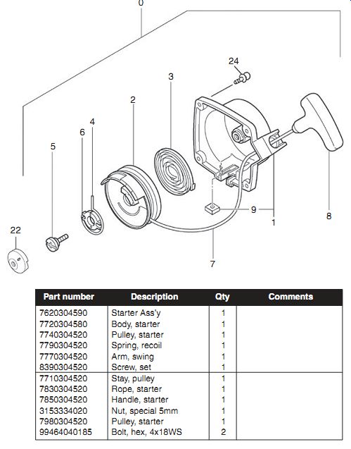
FIG. 8. Tanaka 260 PureFire unit is representative of starters used widely
on Japanese engines.
Japanese generic
Tanaka, Shindaiwa, and several other Japanese manufacturers use versions of the clutched starter shown in Fig. 8. Repair procedures are outlined in the following discussion; for more detail on cord installation refer to the discussion of one-piece sheave Eaton starters.
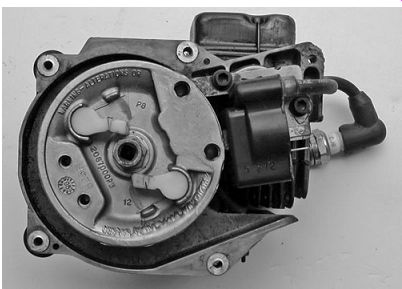
FIG. 9. Ratchets may pivot off the flywheel as shown here or off the sheave.
The hairsprings, barely visible in the photo, are quite fragile.
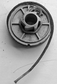
FIG. 10. A toothed wheel transmits starter torque
Disassembly
1. Remove the starter assembly from the shroud.
2. Pull on the handle and, while holding the sheave with your thumb, slip a section of the cord out through the notch provided on the sheave OD.
3. Allow the sheave to unwind in a controlled fashion.
4. With Fig. 8 as the reference, remove the central screw (5) and the swing arm (4), and carefully lift the pulley (2) out of engagement with the main spring. Wear eye and hand protection when handling the pulley and spring.
Assembly
1. Clean hard parts in nonflammable solvent.
2. Check for wear or distortion with particular attention to the main spring anchor points and the swing arm.
3. If the main spring has been disturbed, secure its outboard end to its anchor and carefully feed the spring into the housing, winding it counterclockwise.
4. Lightly grease the spring and the sheave post.
5. Install the sheave and cord, preloading the assembly as described previously.
6. Verify starter function and install the unit on the engine.
Ratchet drive Many handheld tools employ ratchet starters ( Fig. 9). Instead of extend able pawls these starters have spring-loaded ratchets that bear against teeth on the flywheel hub ( Fig. 10). Once the engine starts, the ratchets no longer find purchase and coast idly.
Wacker Neuson WM80 Figure 11 illustrates the ratchet starter used on the Wacker Neuson ("noy son") WM80 engine. The main spring mounts "backward," in that its outer end anchors to the sheave and its inner end to the starter housing. And, unlike most, it drives through a single ratchet.
Cord replacement
The combination of a notched sheave and an accessible cord anchor means that the cord can be replaced without removing the sheave ( Fig. 12).
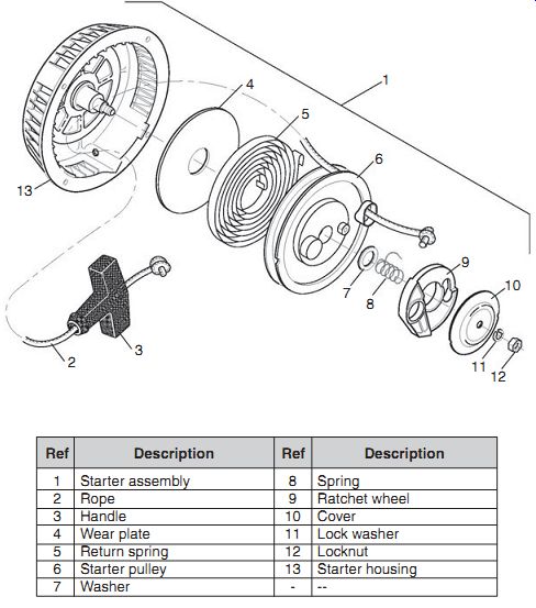
FIG. 11. Critical areas include the bent main spring ends, the washer (7)
which must be installed for the unit to operate properly, and the relation
between the ratchet wheel (9) and its spring (8). The main spring should be
lightly oiled and the sheave shaft greased.
Follow this procedure:
1. Remove the starter assembly from the blower housing.
2. Lift several inches of cord up through the notch on the sheave. While holding the cord to brake the action, allow the sheave to rotate clock wise until spring tension dissipates.
3. Untie the knot and pull the cord from the sheave.
4. Thread the replacement cord through the sheave and up through the anchor hole. Install the handle and knot both ends of the rope as shown in Fig. 12. Trim the end of the cord flush with the knot on the sheave: overhang interferes with starter operation.
5. Lift several inches of cord through the slot and turn the sheave counter clockwise two revolutions, guiding the cord as the sheave turns.
6. After two revolutions, disengage the cord from the notch and permit spring tension to wind the cord on the sheave. Repeat this procedure until all 60 in. of cord are on the sheave and the handle makes positive contact against the housing.
7. Install the starter assembly on the blower housing.
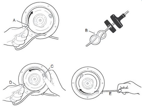
FIG. 12. Wacker Neuson WM cord replacement: disarm the main spring (A), tie
nonslip knots on both ends of the cord (B), rewind the cord (C), and verify
that the cord extends without coil bind and retracts smartly (D).
Disassembly
1. Remove the starter assembly from the flywheel shroud.
2. Release spring tension as described in the previous section. Using Fig. 11 as the reference, undo the locknut (12), lock washer (11), and cover (10). Lift off the ratchet wheel (9), noting its relation ship to the spring (8). The washer (7) is critical for starter operation.
3. Slowly lift the sheave (6) from the starter housing. If necessary remove the return spring (5), working from the center outward.
Warning: Wear eye protection and gloves.
4. Remove the wear plate (4).
Inspection
Return spring. The spring ends should be bent 180° as shown in Fig. 13(A). Distortion can make it difficult to install the spring in its slotted anchors. Clean the parts in nonflammable solvent.
Sheave. Inspect the sheave for wear at the spring anchor. Clean the mounting stud, grease lightly, and test-fit the sheave. It should turn easily without excessive side play.
Ratchet. If the tip (C) is rounded off, the starter may slip on engagement, and the ratchet should be replaced.
Cord. Replace if worn, oil-soaked, or shorter than its specified 60-in. length. Insufficient cord length can damage the starter.
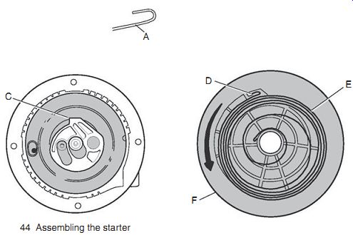
FIG. 13. Wacker Neuson assembly references.
Assembly
1. Except for the cord, clean all parts with nonflammable solvent.
2. Insert the outboard end of the spring into its anchoring slot (D in Fig. 13) on the sheave (F). Wind the spring into the housing being careful to contain the coils within the cavity provided. As mentioned before, protect eyes and hands when dealing with main springs.
Once the spring is installed, lubricate with WD-40.
3. Lightly grease the center post and install the wear plate and sheave.
4. Turn the sheave to engage the center end of the spring with the housing.
5. Install the washer (7 in Fig. 11) over the center post and into the recess on the sheave.
6. Mount the ratchet spring and ratchet wheel. These parts go on dry without lubrication. Install the cover, lock washer and locknut. Torque the nut to 6 ft/lb (8 N·m).
7. Install the cord as described previously.
8. Mount the starter on the engine.
Things to remember
Now that we've gone through the major starter types, you should be able to repair any of them. Important points are:
• The main spring winds tighter as the flywheel is turned in the normal direction of engine rotation. If you trace the curvature of the spring from the fixed outer end to inner end where the sheave anchors, your finger would move in a counterclockwise spiral.
• Eaton-style friction clutches assemble without lubrication. Should the clutch slip, verify that friction elements are dry, the center screw is tight, and the drag spring undamaged.
• Failure of the cord to retract can be caused by loss of pretension, a weak main spring or by misalignment between the starter and fly wheel hub.
Prev. | Next
Home Article
index top
of page