Something like 90% of engine malfunctions that a new spark plug can't fix are caused by the fuel system. The system consists of the fuel tank, filter, pulse and fuel lines, air filter, carburetor, reed valve (when fitted), and engine crankcase. We will discuss each of these components separately.
Fuel tank
Routinely examine the tank for leaks and for loose or stripped hold-down bolts. Mysterious engine shutdowns that elude obvious explanation may be caused by a failed tank vent, which can be integral with the fuel cap or, as in the case of the Tanaka shown in Fig. 1, a separate component.
Fuel filters
Fuel filters should be changed at least every 100 hours of operation and whenever
• Fuel delivery, signaled by no fuel to the carburetor or by a bleached spark-plug, has been compromised,
• Fuel quality is suspect.
Use a hooked wire to retrieve in-tank filters of the kind used on hand held tools. Replace deformed or rusted hose clamps.
Fuel lines
Larger two-strokes use elastomer hose that, in its latest evolution, has a nylon core to reduce evaporative fuel losses. These hoses come in 1/2-, 5/16-, and 3/8-in. IDs.
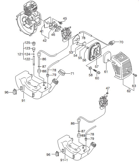
FIG. 1. Tanaka TBC-250 fuel-tank assembly exhibits the sort of detailed engineering
found in professional equipment. Spring clips secure the fuel filter (89) and
the check valve (123). Fuel pipes (78 and 86) make up to a flexible grommet
and, for added leak protection, draws from the top of the tank.
Be skeptical of the plastic lines used on portable equipment to transfer fuel and energize the fuel pump with crankcase pressure pulses. Heat and vibration harden the plastic, which then leaks fuel and, what is more difficult to diagnose, air. Pulse lines are also susceptible to clogging.
Most applications call for 0.110-in. ID by 0.190-in. OD or 0.140-in. ID by 0.230-in. OD lines. To avoid confusion, purchase replacements from a dealer for the engine in question.
The plumbing can be complex. Make a sketch or take digital photos of the routing, which should be well clear of the muffler and other hot spots.
Confusing primer or pulse lines with fuel lines prevents the engine from starting.
To make line-to-tank installation easier, cut end of the plastic line at an angle and lubricate it with motor oil. You may want to stiffen the line with wire. Once the line has passed through the tank, remove the gas cap and use long-nosed pliers or a surgical hemostat to pull several inches out of the tank ( Fig. 2). Trim the end square and install the filter together with the optional hose clamp. Check for leaks before starting the engine and after 30 minutes or so of hard use.
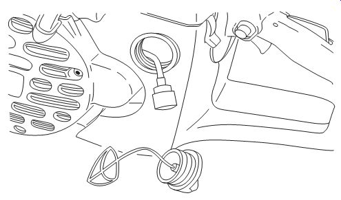
FIG. 2. As this Wacker Neuson illustration shows, there should be enough
slack in the line to allow the filter freedom to respond to gravity as the
tool is tilted off the horizontal.
Air filters
There is some dispute about which filters are better-pleated paper or urethane foam. In theory, paper catches smaller particles, but some field tests indicate that foam reduces engine wear. Foam filters consist of a labyrinth of tiny passages that trap solids along their whole depth. Paper filters, on the other hand, present a surface barrier, which can quickly clog.
Light-duty two-strokes make do with a single foam filter, while better engines combine both types. A foam prefilter stops large particles before they impact the paper main filter. STIHL cutoff saws combine centrifugal filtering with two stages of conventional filtering. Husqvarna uses a similar arrangement on its concrete saws. The company claims that the centrifuge removes 80 to 90% of the dust these tools generate prior to filtration. When the filters clog, Husky carburetors go lean to compensate for the increased pressure drop.
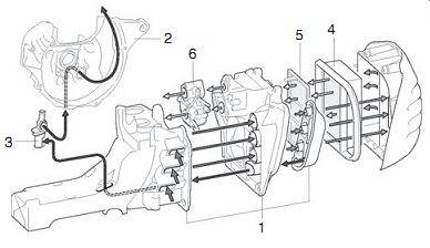
FIG. 3. The STIHL TS 410 cutoff tool combines centrifugal with conventional
filtering. The tank housing (1) acts as a centrifuge to separate out larger
and heavier dust particles. Contaminated air passes through the molded hose
(3) to the fan side of the crankcase (2) and into the atmosphere. Pre-cleaned
air undergoes two stages of filtering (4) and (5) before entering the carburetor
(6). This system requires very little maintenance. Change the filter only if
the engine shows loss of power or if more than a year of extended used has
passed since the last filter change. Attempts to clean the filter damage it.
Inspection
As filters collect dirt, they become more restrictive. The increased pressure drop sends the carburetor rich. The engine loses power, the spark plug turns darker, and the exhaust becomes acrid. Paper filters are also sensitive to moisture. Some filter housings give little protection against rain and any can be defeated with a pressure washer. When this happens, the cellulose fibers swell and close off the air channels. Solvents or oil leached from the prefilter have a similar effect. When in doubt, replace the paper element.
Servicing
Remove the filter cover and carefully wipe off dust on the housing with a moist shop towel. Dust entry during filter service is a major cause of engine damage. Wash foam filters in warm water and detergent. Rinse, dry, and apply the proper wetting agent, available from Husky and other dealers. Motor oil quickly gets sucked into the carburetor.
Paper filters are throwaways, impossible to clean. Blowing out the filter with compressed air releases a satisfying cloud of dust, while at the same time blasting microscopic holes in the media. Replace the filter with a factory (and not a Chinese aftermarket) part.
Carburetors
In a chemically perfect world, engines would consume 14.7 grams of air for each gram of fuel. This is called the stoichiometric ratio. Unfortunately, the ideal can only be approximated a part throttle and under light loads. For best power, a two-cycle engine needs a mixture ratio of between 12 and 13:1. And, if the engine is to live at wide open throttle, the mixture should be richened further to 11 or even 10:1. The surplus gasoline functions as a coolant. Cold starting and idle require even richer mixtures as indicated in:

Tbl. 1.
Tbl. 1
Air-fuel mixture ratios for different operating conditions
To accommodate the wide range of mixture requirements, carburetors employ at least two fuel circuits: high-speed and low-speed. In addition, carburetors have a restriction, called a venturi, to build vacuum in the throttle bore and a throttle valve to control engine speed. A diaphragm or float valve regulates the level of fuel in the instrument.
Diaphragm carburetors
Because diaphragm carburetors are insensitive to attitude-the diaphragm functions in any position, even inverted-they are standard on trimmers, hedge clippers, and other handheld tools. The trade-off is less-than-perfect control over the mixture and reduced reliability.
Sometimes a carburetor can be returned to service by merely replacing the diaphragms and squirting carburetor cleaner into places that look important ( Fig. 4). But if repairs are to be more than a matter of luck, one needs to understand what goes on in these little cubes of aluminum.
Critical areas are the diaphragms, inlet needle, low- and high-speed circuitry, and the provision for cold starting. All carburetors have these elements, which work in the same general fashion. Once you have come to terms with them, you should be able to repair Tanaka, Tecumseh, Zama, and all but a handful of Walbro carburetors.
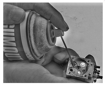
FIG. 4. New diaphragms and carburetor cleaner can sometimes "fix" a
carburetor to the extent that the engine starts and runs.
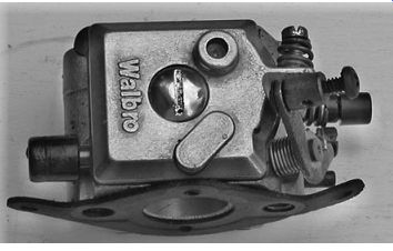
FIG. 5. Pumps on smaller carburetors usually are on the side opposite the
metering diaphragm.
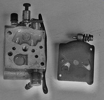
FIG. 6. Pump with cover removed. The flap-like cutouts in the diaphragm function
as inlet and outlet valves.
What remains are bells and whistles, such as the accelerator pumps and speed-limiting governors found on high-end instruments. While these features have technical interest, they exert little impact upon repair work.
Fuel pump
Most handheld engines employ a fuel pump, mounted on the carburetor body ( Fig. 5). The pump element consists of a nitrile diaphragm, with flaps cut into it that act as inlet and output check valves ( Fig. 6). The cavity cast into the pump body is a variable-displacement fuel reservoir, whose volume changes as the diaphragm, which forms the floor of the cavity, flexes.
As the piston rises toward top dead center (TDC), it leaves a partial vacuum behind it in the crankcase ( Fig. 7). This vacuum, transmitted to the outboard side of the diaphragm by a drilled passage in the carburetor body or by an external line, pulls the diaphragm down, away from the fuel cavity. Because of the increase in its volume, a slight vacuum is created in the cavity. Fuel, under atmospheric pressure in the tank, rushes in past the open inlet valve to fill the void. The pump is now charged.
A few milliseconds later, the piston rounds TDC. As it travels down the bore, it pressurizes the crankcase to 5 or 6 psi above atmospheric. The pressure forces the pump diaphragm upward into the cavity ( Fig. 8). The inlet check valve closes to prevent fuel from cycling back to the tank. At the same time, the discharge valve opens, admitting pressurized fuel into the carburetor.
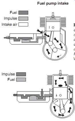
FIG. 7. As the piston rises, it evacuates the crankcase. The negative pressure
pulse, acting on the underside of the diaphragm, pulls the diaphragm down and
away from the fuel cavity. During this phase, the inlet flap valve opens and
the outlet valve closes. Impelled by atmospheric pressure, fuel enters the
cavity.
FIG. 8. Crankcase pressure forces the diaphragm upward, opens the outlet valve, and closes the inlet valve. Fuel flows into the carburetor body.
Pumps fail progressively, pumping less fuel as the diaphragm hardens and loses elasticity. Loss of power under full load is the first symptom. However, a partially clogged main jet or inlet screen (including the one sometimes found downstream of pump discharge) can have the same effect. Air leaks at fuel- or pulse-line connections usually are severe enough to prevent starting.
The same holds for obstructions in the pulse line. Another cause of failure is incorrect assembly: the diaphragm and gasket must be installed in the correct sequence. Some pumps go together with the gasket against the carburetor body, followed by the diaphragm. Others reverse the sequence.
Metering
Metering is the term used to describe the ability of the carburetor to regulate mixture strength under varying loads and speeds. The position of the throttle determines the volume of air available for combustion; four components control the amount of fuel supplied to the jets ( Fig. 9):
• Metering diaphragm
• Inlet needle
• Inlet lever
• Lever spring
Unlike the fuel pump, which dances to crankcase pulses, the metering diaphragm responds to variations in inlet-pipe vacuum. The underside of the diaphragm vents to the atmosphere; the upper, or wet, side sees the same vacuum that draws fuel into the carburetor bore. During the moments of peak vacuum the diaphragm lifts and presses against the lever. This action overcomes the spring tension that holds the needle closed. The needle then unseats in response to 5 or 6 psi of pressure created by the fuel pump. Fuel flows past the unseated needle into the space above the diaphragm, known as the metering chamber.
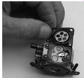
FIG. 9. Most carburetors transfer movement from the diaphragm to the needle
by way of a spring-loaded lever. The lever is the bright metal part shown at
2 o'clock in the photo.
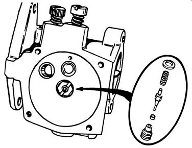
FIG. 10. Tecumseh/Tillotson direct-acting inlet needle.
A few milliseconds later, the inlet port closes. Manifold vacuum drops, causing the diaphragm to relax its pressure on the lever. The inlet needle, now under spring tension, closes to cut off fuel delivery.
Fuel delivery depends upon two variables: the tension of the lever spring and lever height. Substituting a weaker spring for the stock item increases fuel flow by reducing the workload on the diaphragm. A similar effect can be had by raising the lever, so that it comes into play earlier and allows the needle to stay open longer.
In addition to supplying fuel for steady-state operation, the metering system must provide the rich mixtures needed for acceleration and inhibit fuel delivery during coast-down. How well the engine behaves during these transitional modes depends upon the resilience of the diaphragm, the relationship between the lever and diaphragm, and spring tension. While factory defaults are not written in stone, one should exert extreme caution when swapping springs and experimenting with different lever heights.
But not all of these instruments employ a lever. Figure 10 shows the inlet needle and associated parts for a Tecumseh carburetor. The diaphragm bears directly against the needle without the intermediary of a lever. The Tillotson also has a replaceable needle seat, a welcome feature not always found on these carburetors.
The relationship between the diaphragm gasket and diaphragm is critical.
Some carburetors assemble with the gasket next to the carburetor body; others have the gasket next to the cover. It pays to have a notebook handy when disassembling unfamiliar equipment.
A hole in the metering-chamber cover vents the underside of the diaphragm to the atmosphere. The vent also enables the carburetor to be primed for easier starting. This is done by inserting a small Allen wrench into the vent and gently pressing the diaphragm upward to unseat the inlet needle.
The inlet needle causes a disproportionate amount of trouble. A tiny spring, which looks like it could have come from a watch, holds the needle closed. To generate adequate unit pressure, the needle contacts the seat along a narrow band. A microscopic spec of dirt is enough to compromise the seal. And because all that opens the needle is fuel-pump pressure acting against its tip, the needle tends to stick closed. The good news is that a squirt of aerosol carburetor cleaner is usually enough to set things right.
Venturi
A carburetor bore resembles an hour glass, wide at the ends and narrow at the center. The necked-down section, known as the venturi, causes the incoming air stream to accelerate and lose pressure ( Fig. 11).
To understand why, consider that the venturi is open at both ends. As much air leaves as enters, but the restriction increases the distance air travels, which means that air velocity must also increase. Since nothing in nature is free, velocity comes at the cost of pressure.
The same principle explains why airplanes fly. The upper surface of the airfoil is curved and the lower surface flat. Air passing over the top of the wing loses pressure relative to air moving under it. The pressure differential is felt as lift.
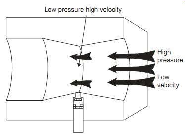
FIG. 11. A venturi generates negative pressure and increased velocity.
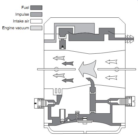
FIG. 12. The high-speed circuit flows in response to venturi vacuum.
High-speed circuit
The vacuum created by the venturi draws fuel from the metering chamber through the high-speed jet and discharge nozzle ( Fig. 12). The nozzle, located near the narrowest point of the bore, begins to flow at around quarter throttle. As the throttle opens wider, the vacuum produced by increased air flow draws greater amounts of fuel through the nozzle to keep pace with engine demands.
In the past, nozzles were threaded into the carburetor body and could be removed for servicing. Most modern carburetors have pressed-in nozzles that should not be disturbed.
The size of the main jet determines the rate of fuel delivery through the nozzle. Depending upon the carburetor, the jet may be fixed or adjustable, removable or not. But all main jets have one characteristic in common: as the most restrictive component in the high-speed circuit, they are the first to clog.
Low-speed circuit
On most carburetors, the low-speed circuit discharges through a row of holes drilled into the carburetor body, adjacent to the throttle plate. The nomenclature varies: most technicians refer to the first hole, the one closest to the engine, as the idle port. Those that remain are called progression or transition ports.
At idle, the throttle is almost closed, a condition that divides the carburetor bore into two pressure zones. Low pressure exists on the engine side of the throttle and atmospheric pressure on its upstream side. Impelled by the low pressure, fuel enters through the idle port ( Fig. 13). Air, under atmospheric pressure, enters through the transition ports to mix with the fuel before discharge. Aerating the fuel assists in atomization and helps prevent fuel puddling in the intake pipe and crankcase.
As the throttle cracks open, the transition ports come under inlet-pipe vacuum and pass the additional fuel needed as the engine speeds up ( Fig. 14). At some point near quarter throttle, air flow through the venturi generates enough vacuum to energize the high-speed circuit.
The idle jet works in tandem with the idle and transition ports to deter mine the amount of fuel delivery. Most idle jets, even those on emissions carburetors, have some limited provision for adjustment: backing the adjustment needle out of the jet orifice richens the mixture by allowing more fuel to flow for the same amount of air.
Nozzle check valve
The discharge nozzle incorporates a one-way valve, in the form of a ball or a plastic disk. At mid- and high speeds, air flow through
the venturi generates enough vacuum to unseat the check valve and permit fuel to flow through the nozzle ( Fig. 15). At idle and part throttle conditions are reversed. The venturi comes under atmospheric pressure and the pressure in the metering chamber drops as the low-speed circuit consumes fuel. The check valve closes. Were the valve to remain open, air under atmospheric pressure would enter the metering chamber via the nozzle. The metering diaphragm, denied the low pressure necessary to unseat the inlet needle, would hang motionless. A sticking nozzle check valve has no effect upon high-speed operation. But the engine quickly runs out of fuel at idle.
Some Walbro carburetors substitute a fine-mesh screen for the check valve. Surface tension of fuel on the mesh is enough to prevent air entry into the nozzle. Should the screen clog, fuel will be denied at wide throttle angles.
Cold start
The reluctance of gasoline to vaporize at ambient temperatures coupled with low cranking speeds, makes cold staring difficult. Extremely rich mixtures are required.
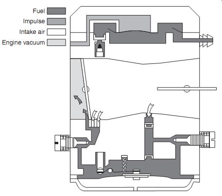
FIG. 13. At idle, the throttle plate is nearly closed and fuel flow is confined
to the idle port. Transition ports, upstream of the idle port, aerate fuel
awaiting discharge in the idle pocket. The low-speed jet shown here is adjustable.
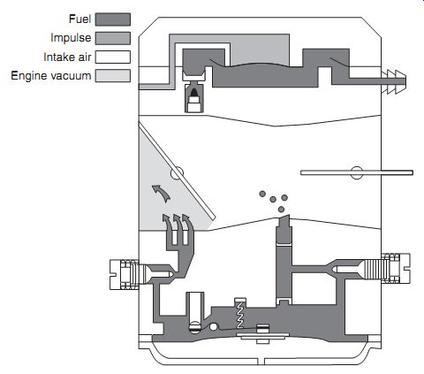
FIG. 14. Off-idle operation draws fuel from the idle port and the two transitional
ports. Greater throttle angles energize the venturi and the high-speed circuit.
The degree of overlap between low- and high-speed systems varies with carburetor
design.
Choke
The simplest way to increase fuel flow is to seal off the carburetor bore with a choke valve upstream of the venturi. When the valve is closed, all circuits come under vacuum and pass fuel ( Fig. 16). Nothing could be simpler and less liable to failure. On the downside, the operator must calculate how much choke a semi-warm engine needs. Insufficient choking starves the engine; over-choking drowns it.
The choke also functions as a diagnostic aid: a warm engine that runs better with the choke engaged ingests air downstream of the carburetor.
Expect to find loose carburetor hold-down bolts, a torn flange gasket, or leaking crankshaft seals.
Purge pump
The heart of the purge system is a rubber bulb that can be mounted on the carburetor or at some position more convenient for the operator. Like any pump, the bulb works in conjunction with inlet and out let check valves.
Pressing on the bulb opens the outlet check valve to displace any air in the system back through a line to the tank. Releasing the bulb closes the outlet check valve, isolating the tank, and opens the inlet valve to apply vacuum to the metering chamber ( Fig. 17). The metering diaphragm responds to the vacuum, the inlet needle unseats, and fuel flows into the metering chamber, past the open inlet valve, and into the bulb ( Fig. 18).
When the transparent bulb is full of fuel, the carburetor is primed.
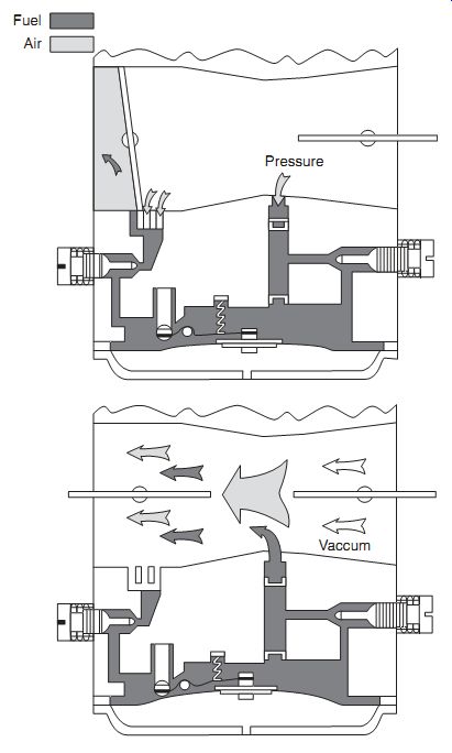
FIG. 15. At small throttle angles, the venturi comes under atmospheric pressure
and the nozzle check valve closes. Opening the throttle increases air flow
through the venturi, a condition that generates the negative pressure. When
this happens, the check valve lifts and fuel flows through the nozzle.
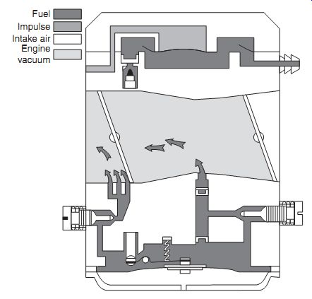
FIG. 16. Cranking with the choke closed evacuates the carburetor bore and
all circuits flow.
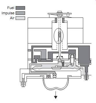
FIG. 17. Releasing the bulb closes the discharge check valve and opens the
inlet check valve.
The vacuum created as the bulb expands lowers the metering diaphragm and unseats the inlet needle.
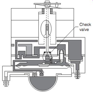
FIG. 18. When the bulb is full of fuel, the carburetor is purged of air and
primed to deliver a rich starting mixture. The check valve prevents air from
entering the metering system through the discharge nozzle as the bulb inflates.
This valve does not replace the nozzle check valve, used on butterfly throttle
carburetors as illustrated in Fig. 15.
An additional check valve blocks air entry from the idle circuit.
Primer pump
Purge and primer systems both employ an elastomer bulb as the pump element and cycle entrapped air back to the fuel tank. But, rather than merely lifting the inlet needle, a primer delivers a shot of raw fuel into the carburetor air horn. Over-enthusiastic priming can flood the engine.
Pressing the bulb draws air out of the circuits; as the bulb recovers shape, it fills with fuel. Pressing it again sends fuel into a storage compartment or to a wick. For some carburetors, wick saturation is not automatic; in addition to pressing the bulb twice, the operator must also press the starter button on the underside of the carburetor body ( Fig. 19).
Accelerator pumps
Snap the throttle open and the sudden onrush of air fills the intake pipe. Manifold vacuum momentarily drops to zero. Robbed of vacuum, the carburetor no longer provides sufficient fuel. The inertia of gasoline vapor compounds the problem. The engine hesitates and, in extreme cases, announces its distress with backfires.
The traditional cure for hesitation is to mask the problem with high idle rpm-some two-strokes idle at 3000 rpm-and rich idle mixtures. A better approach, and one more compatible with emission requirements, is to incorporate an accelerator pump.
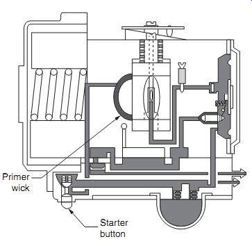
FIG. 19. This Walbro barrel-valve carburetor employs a wick that is wetted
by the primer pump when the bulb is pressed twice and the starter button held
down.
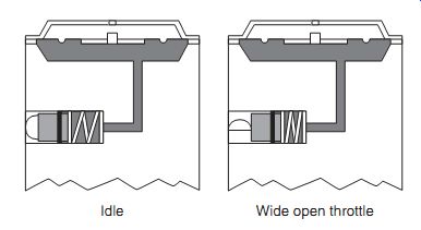
FIG. 20. A piston-type pump, keyed to throttle motion, represents the most
direct approach to mixture enrichment.
Piston-type pump
Some carburetors employ a spring-loaded brass piston as the pump element. At low speeds, the piston rests on flat spot milled on the throttle shaft. As the throttle swings open, it cams the piston forward to force fuel into the carburetor bore or metering chamber ( Fig. 20). Pulse-driven enrichment Pulse-driven enrichment works by exciting the metering diaphragm with positive pressure pulses from the crankcase. A passage in the carburetor body runs from the crankcase to the throttle shaft.
When the throttle opens, a hole in the shaft aligns this passage with a second passage that leads to the dry side of the metering diaphragm ( Fig. 21).
Normally the dry side of the diaphragm sees only ambient pressure. Piping in crankcase pulses increases fuel delivery so long as the throttle remains open.
Boot pump
This approach to mixture enrichment uses a flexible boot as the pump element ( Fig. 22). At small throttle angles, the boot distends with fuel. Opening the throttle exposes the outer surfaces of the boot to crankcase pulses. The pressure differential collapses the boot, forcing fuel into the carburetor air horn.
Governor
The governor consists of a spring-loaded ball that vibrates to augment fuel delivery at a pre-set engine rpm. The brass capsule, slotted for a screwdriver, mounts externally some Tillotson and Walbro carburetors.
Most tuners adjust a carburetor by setting the mixture needles halfway between lean and rich drop-off. The high-speed adjustment requires a generous amount of throttle. If a governor is present, it will richen the high speed mixture as the rpm limit is approached. Tightening the high-speed adjustment needle has little effect upon fuel delivery, making it impossible to find lean drop-off. The way around this problem is to make the adjustment while the engine is under load.
Barrel-valve carburetors
Most Zama and some Walbro carburetors regulate fuel delivery mechanically with a barrel throttle and tapered needle that extends into the main nozzle. These instruments dispense with low speed circuit: all fuel enters through the nozzle.
The Walbro range consists of the WY ( Fig. 23) and the WZ series ( Fig. 24), with the former distinguished by the build-in air filter and the right-angle turn entering air makes. Variations of the WY series currently extend in alphabetical order from the WYE through WYP. The WYF is the lone example of a float-type, barrel-valve carburetor. All WYs have pump and metering diaphragms stacked on the same side of the plastic or metal carburetor body.
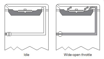
FIG. 21. Some Walbro carburetors use crankcase pulses to richen the mixture
at large throttle angles.
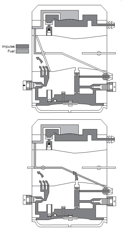
FIG. 22. A boot-type accelerator pump charges at small throttle angles, as
shown in the upper drawing. Opening the throttle directs positive crankcase
pulses to the dry side of the boot, which empties itself directly into the
carburetor bore or by way of the metering chamber.
Figure 25 illustrates how fuel and air are metered. The obstruction presented by the barrel creates negative pressure at the discharge nozzle. At low speeds, the barrel (A) and needle (B) restrict air and fuel flow. As the barrel rotates open, it cams upward and lifts the needle higher in the discharge nozzle (C). Retracting the tapered needle increases the effective area of the nozzle and more fuel flows. At higher speeds, the cross-drilled pas sage in the barrel comes into better alignment with the axis of the carburetor bore. Thus, air delivery keeps pace with fuel delivery.
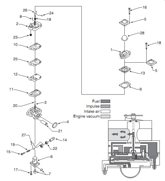
FIG. 23. The Walbro WY barrel-valve carburetor piggybacks the pump and metering
chamber. In most examples the jet is fixed and non-replaceable.
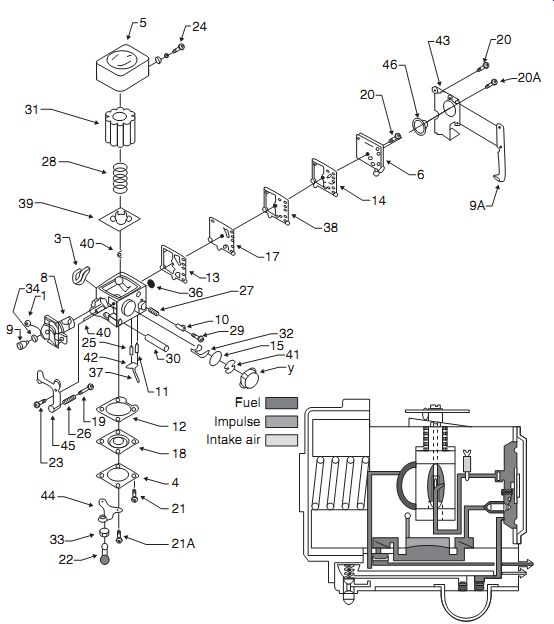
FIG. 24. The Walbro WZ barrel-valve carburetor has fuel pump and metering
diaphragms on opposite sides of the main casting. The primer bulb mounts on
the pump cover, which also houses a removable check valve.
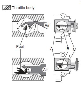
FIG. 25. Barrel-valve carburetor operation.
Troubleshooting diaphragm carburetors
Carburetors cause a disproportionate amount of trouble, but by no means are the only source of problems. Before rushing to judgment
• Drain the fuel tank and add fresh premix with the correct amount of lubricant.
• Replace the fuel filter.
• Clean or replace the tank vent valve.
• Visually inspect fuel lines for leaks and hardening.
• Verify that the engine generates at least 90 psi of compression during open-throttle cranking.
• Check ignition output.
• Replace the spark plug with a correctly gapped and known-good plug of the same type as originally installed.
• Service the air filter. Clean foam filters, and pre-filters; replace paper main filters.
Tbl. 2 is a general guide, listing the effects of carburetor malfunctions upon engine behavior. Note the degree of overlap-any of a dozen carburetor faults have the same or similar effects upon engine performance. Within reason, try to cover all bases by changing out each of the parts supplied in the repair kit.
Pressure tests
Readers who intend to do much carburetor work should purchase a Walbro PN 500-500 tool kit, available from factory distributors.
The kit includes cape chisels and punches for dealing with Welch plugs, a slide hammer, and, most importantly, a PN 57-11 pressure tester. Any of these tools can be purchased separately. Other sources of pressure testers include snowmobile and motorcycle dealers. If you have an automotive cooling system leak tester, you can adapt the hose connection to mate with the carburetor inlet fitting.
Metering-system function
The first priority is to determine if the metering system, the source of most problems, functions. Connect the tester to the carburetor inlet fitting and pressurize the circuit to 6 or 7 psi, the equivalent of fuel-pump pressure. The gauge should hold steady ( Fig. 26).
Tbl. 2 Diaphragm carburetor malfunctions and their effects upon performance
----------------
[Carburetor faults Improperly adjusted low-speed mixture needle Improperly adjusted high-speed mixture needle Plugged fuel-tank vent Defective fuel line-clogged or leaking air N and/or fuel Clogged fuel passage in carburetor body Clogged fuel screen Pump failure-loose cover, leaking gasket, N defective diaphragm, blocked fuel channels, clogged fuel screen (when fitted), clogged or leaking pulse line Metering system failure-hardened or leaking diaphragm, worn or sticking inlet needle, leaking diaphragm gasket, loose Q metering chamber cover Metering lever set too high and/or distorted lever spring Metering lever set too low and/or distorted lever spring Carburetor faults Defective discharge-nozzle check valve E (butterfly-throttle carburetors)
Air leak downstream of venturi- carburetor-mounting flange, severe wear E on throttle shaft, crankshaft seals ]
[ Effects on performance
Hard starting Refusal to idle Stumble upon acceleration Engine quits when closing throttle
Will not run at WOT* Loss of power Quits when closing throttle Hard starting Shutdown after a few minutes of operation Refusal to idle Hesitation or refusal to accelerate Engine will not run at WOT Loss of power
No or hard starting Refusal to idle Hesitation or refusal to accelerate Engine will not run at WOT Loss of power
No or hard starting
Refusal to accelerate
Quits when closing throttle
Will not run at WOT Loss of power No or hard starting
Hesitation or refusal to accelerate
Quits when closing throttle
Will not run at WOT Loss of power
Overly rich mixture
Idles with mixture adjustment screw closed Fuel drips from air horn Quits when closing throttle Erratic idle
Excessively lean mixture
Will not run at WOT Loss of power Hesitation or refusal to accelerate
Effects on performance
Erratic idle
Hesitation or refusal to accelerate Quits when closing throttle
No or hard starting
Excessively lean mixture
Erratic or no idle Hesitation or refusal to accelerate Will not run at WOT Loss of power Performance improved with choke closed
]
--------------------
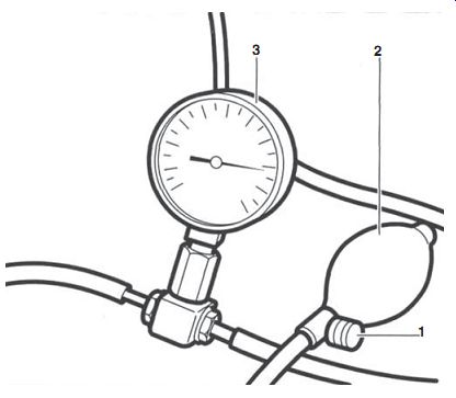
FIG. 26. Pressurize the carburetor through the fuel inlet fitting to 6 or
7 psi.
Failure to hold pressure indicates an inlet needle that does not properly seat or a leaking fuel pump diaphragm. A STIHL PN 0000 850 1300 can also be used to test the integrity of the crankcase.
Close the choke or insert a rag into the carburetor air horn to gain vacuum assist. Pull the engine through several times and note how the gauge responds.
If all is well, the gauge needle will flicker as the inlet needle opens and reseats.
If the gauge holds steady, the metering system has failed. Expect to find a stuck inlet needle, a defective diaphragm, or a leaking metering-chamber gasket.
Pop-off and reseat pressure measurement
It can be helpful to quantify inlet-needle response. With the tester connected to the carburetor inlet fitting, slowly increase pressure. At some point not always well defined by the literature, pressure will abruptly drop as the inlet needle unseats, or pops off. The reading should then stabilize as the needle returns to its seat.
Ultralight pilots, whose lives depend on their engines, spend hours tinkering with lever adjustments and springs to obtain consistent pop-off and reseat pressures. For less critical applications pop-off pressures can vary by more than 10 psi for otherwise identical carburetors. Reseat pressures are also a little vague, but we need something on the order of 10 psi to close the needle against pump pressure.
Immersion tests
If the carburetor fails to hold pressure, immerse it in clean solvent. Bring pressure back up to 7 psi and trace any bubbles back to their sources. If, for example, bubbles stream out the vent hole in the metering-chamber cover, the diaphragm leaks. Remove the cover and repeat the test. There should be no bubbles from the inlet needle until it pops off.
Some carburetors may exhibit a few random bubbles from the pump housing without ill effect.
No start
Refusal to start can nearly always be laid to insufficient fuel delivery.
The spark plug tip will remain dry after extended cranking. A pressure tester will show if the inlet needle unseats, but its good practice to spray a small amount of carburetor cleaner into the spark-plug port. If the engine runs and quits after a few seconds, you can be confident that it suffers from fuel starvation. The fact that the engine runs at all certifies the ignition system.
But there could be a problem with fuel ingestion. In order to verify that the engine can, as it were, feed itself, spray carburetor cleaner into the air horn.
Failure to ingest carb cleaner means that we have a major air leak some where downstream of the carburetor. Check carburetor hold-down screws, the mounting flange gasket, and, if it comes to it, the crankcase seals as described in Section 6.
Warning: Confine the spray to the carburetor throat and replace the filter element, which acts as a spark arrestor, before cranking. Carburetor cleaner is extremely flammable.
No gasoline delivery can have several causes. If you have not already replaced the fuel filter, replace it now. The next most likely culprits are leaking fuel and/or fuel-pump impulse lines. With plastic lines one must intuit the presence of an air leaks by how hard the lines are and by their age. When in doubt, replace them. Check the impulse circuit for clogs, which are most likely to develop at the engine casting. Carbon collects in the crankcase side of the port. Remove the carburetor, squirt a little oil into the impulse port, and crank. If the port is open, oil will spill out.
If you do not have a carburetor tester pump, replace the inlet needle and seat as a matter of course. Do the same for the metering and pump diaphragms.
Refusal to idle
Refusal to idle can mean that the engine dies when the throttle is closed or that a closed throttle does not bring rpm down. If the latter is the case, look for
• Maladjusted idle stop screw, also known as the idle rpm screw. Refer to the "External Adjustments" section below.
• Maladjusted throttle cable. The cable should be slightly slack with the throttle resting against the idle stop screw.
• An obstruction in the low-speed circuit, usually at the jet or at the discharge ports adjacent to the throttle blade. Backing out the low-speed adjustment needle compensates for a partial blockage. Removing the needle and squirting carburetor cleaner into its boss can sometimes cure more serious blockages..
Caution: Blowing out assembled carburetors with compressed air is a prescription for trouble. Pipe cleaners can be used to clear main fuel and air passages, but jets and discharge orifices must be cleaned chemically.
A leaking main nozzle check valve inhibits idle by bleeding air into the low-speed circuit. In theory, one can test this and other check valves by blowing on them through a tube cut square to make good contact with the carburetor body. A functional check valve opens to pass air in one direction and closes in the other direction. It's good practice to replace check valves, assuming that the parts are available and that disassembly can be accomplished with discretion.
Erratic idle
The most common cause of erratic idle is a low-speed mixture needle adjusted to the point of either rich or lean drop-off. Other possible causes are a metering-diaphragm lever set too high, a distorted or incorrectly sized metering spring, or a leaking nozzle check valve.
Many idle-related problems come about because fuel vapor drops out of suspension and coalesces on the intake pipe and crankcase walls. Some puddling cannot be avoided, since the swirl imparted to the charge in the crankcase coats the crankcase walls with fuel. The motion of the crankshaft and connecting rod has a similar effect. About all that can be done to alleviate the situation is to adjust the low-speed mixture screw as lean as decent acceleration permits.
Some two-strokes employ air-vane governors that, when fitted with the wrong or distorted springs, cause the engines to hunt, that is, to gain and lose rpm in a rhythmic fashion.
Poor acceleration
A stumble or flat spot during acceleration indicates that the mixture is too lean. If a conventional (non-wick) accelerator pump is fitted, blipping the throttle should send a stream of fuel into the carburetor bore. Carburetors without accelerator pumps need a rich low-speed mixture, even at the expense of a smooth idle. Back out the low-speed mixture screw as required. A stiff metering spring or a metering lever adjusted too low also results in lean mixtures and hesitation upon acceleration.
Poor high-speed performance
A ragged exhaust note, loss of power, or failure to attain governed rpm generally come about because of insufficient fuel delivery. Look for gum deposits on the main jet, a sticky main nozzle check valve, soft fuel lines that collapse under the increased draw at high speed, and leaking or hardened diaphragms. A faulty tank vent can produce the same symptoms as can restricted exhaust ports.
Check the integrity of the carburetor flange gasket and, if all else fails, the crankcase seals.
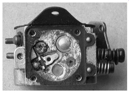
FIG. 27. Water damage has consigned this carburetor to the scrap barrel.
Servicing diaphragm carburetors
Once you made a thorough diagnosis, repairs are anti-climatic. But do not expect miracles. Nothing can be done for carburetors like the one in Fig. 27.
The next priority is to obtain a repair kit. Some engine makers refuse to catalog these kits, preferring to sell new carburetors instead. But carburetors are off-the-shelf items, used on a variety of engines. Shop around and you can find the parts.
Gasket kits contain diaphragms and the necessary gaskets. Repair or overhaul kits include, or should include, an inlet needle, lever spring, lever, check valves, low-speed and (when fitted) high-speed adjustment needles, Welch plugs, and an inlet screen. These are all the parts normally needed.
Figure 28 describes areas of concern.
-------------
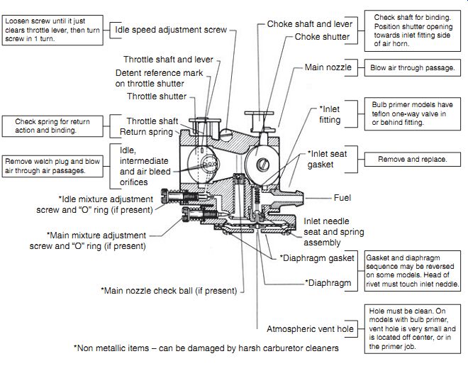
FIG. 28. Repair guide for small Tecumseh diaphragm carburetors has general
application.
Throttle shaft and lever Idle speed adjustment screw
Detent reference mark on throttle shutter Throttle shutter Throttle shaft Return spring Idle, intermediate and air bleed orifices
*Idle mixture adjustment screw and "O" ring (if present)
*Main mixture adjustment screw and "O" ring (if present)
*Main nozzle check ball (if present)
*Non metallic items - can be damaged by harsh carburetor cleaners Atmospheric vent hole
*Diaphragm
*Diaphragm gasket Inlet needle seat and spring assembly Fuel
*Inlet seat gasket
*Inlet fitting Main nozzle Choke shutter Choke shaft and lever Check shaft for binding.
Position shutter opening towards inlet fitting side of air horn.
Loosen screw until it just clears throttle lever, then turn screw in 1 turn.
Check spring for return action and binding.
Remove welch plug and blow air through air passages.
Blow air through passage.
Bulb primer models have teflon one-way valve in or behind fitting.
Remove and replace.
Gasket and diaphragm sequence may be reversed on some models. Head of rivet must touch inlet needle.
Hole must be clean. On models with bulb primer, vent hole is very small and is located off center, or in the primer job.
---------------
Keep a notebook handy to record the routing of fuel lines, the depth of any Welch or cup plugs that you remove, and the gasket/diaphragm sequence.
Cover the work table with paper and lay out the parts in sequence of disassembly. Clean passageways and orifices with an aerosol carburetor cleaner, Q-tips, and pipe cleaners. As the writer can attest, clearing jets with a wire torn from a wire brush upsets the calibration.
Warning: Aerosol spray cleaners contain toluene and other carcinogenic solvents. Work in a well ventilated area, wear gloves, and protect your eyes.
The proliferation of plastic parts and problems associated with safe disposal pretty well eliminate the use of immersion cleaners. Consider products such as Bendix Econ-Clean as a last, desperate resort. Do not allow a carburetor to soak in cleaner for more than 15 minutes and rinse thoroughly with water. A liberal coating of WD-40 (WD stands for "water displacement") prevents corrosion.
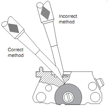
FIG. 29. The Walbro PN 500-500 tool kit includes a cape chisel for removal
of Welch plugs and correctly sized drivers for plug installation.
Welch plugs
There are times when one must remove Welch and expansion cups for access to internal circuits, but do not rush into the job.
Figure 29 shows correct and incorrect ways to attack a Welch plug.
The chisel goes in at a shallow angle to avoid scarring the carburetor body.
Note the depth of the plug and puncture it in the center, well clear of its aluminum boss. Small expansion cups can be drilled and extracted with a sheet-metal screw and Vise-Grips.
Coat the edges of replacement Welch and expansion cups with fingernail polish and, using the appropriately sized pilot, tap the plugs into place.
Lever adjustment
As a very general rule of thumb, most metering levers are adjusted to stand flat or just below the surrounding metal. Zama, for example, calls for the metering needle to be 0 - 0.3 mm (0 - 0.012 in.) below the carburetor body. A depth gauge can be used in the absence of the proper factory gauge ( Fig. 30).
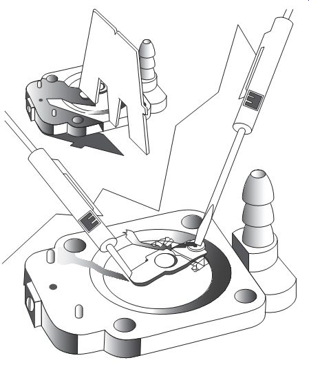
FIG. 30. Walbro throttle levers adjust with a factory gauge. While holding
a small screwdriver against the needle-just hard enough to stabilize it-pass
the appropriate gauge over the lever. Adjusted correctly, the lever exerts
an almost imperceptible drag on the gauge.
If the lever is too high, bend down on the free end. If too low, pry up on the end , being careful not to damage the needle and seat in the process.
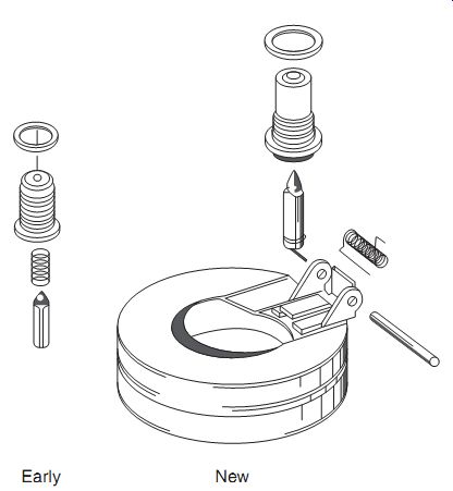
FIG. 31. Typical float mechanism, shown with early and late needles.
Float-type carburetors
Float carburetors give more precise control over the mixture than diaphragm types and cost no more to manufacture. But float mechanisms are gravity sensitive and cease to be reliable at angles of 30° off the horizontal.
Consequently, their use is limited to motorbikes, snowmobiles, outboard motors, and other applications that, hopefully, stay upright.
Float mechanism
As the level of fuel in the float bowl drops, the hinged float falls away from the inlet needle. Fuel flows past the needle and into the bowl at a much higher rate than the engine can use. The level in the bowl rises, lifting the float and forcing the needle against its seat. The primitive, toilet-tank appearance of these valves belies their sophistication. At wide open throttle the needle seats and unseats 200 times a second.
Figure 31 illustrates a "doughnut" float and two versions of the needle and seat. An old-style needle, shown on the left, is made of chrome steel and mates against a brass seat threaded into the carburetor casting. The needle on the left has a Viton tip that, like an automobile tire, flexes to reduce wear.
Other carburetors go the opposite route with a Viton seat and steel needle.
In order for the carburetor to function, the float bowl must come under atmospheric pressure. Some bowls vent through an external hose, routed high to allow the engine to tilt without spilling fuel. Others draw air through an internal passage that opens to the air filter.
Float-type carburetors fall into two groups distinguished by the style of throttle.
Butterfly throttle
Most American-made float carburetors have a butterfly throttle, as shown in Fig. 32. If we disregard the float mechanism, operation is similar to diaphragm carburetors.
Servicing Figure 33 lists service requirements.
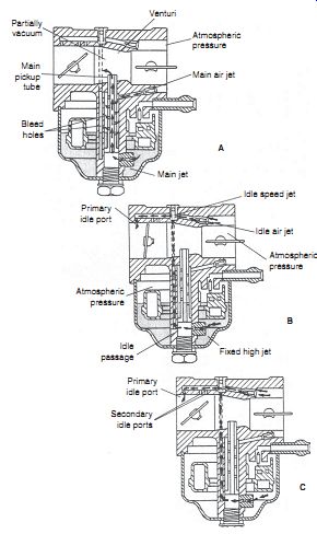
FIG. 32. Float-type carburetor operation. At high speed, fuel enters the
bore through the main pickup tube or, as other manufacturers would have it,
the main nozzle (A). An air bleed atomizes the fuel prior to discharge. At
idle, fuel enters the bore via the primary idle port (B). The (almost always)
adjustable idle speed jet and the idle air jet control low-speed mixture strength.
As the throttle opens wider, the secondary, or off-idle, ports come into play
(C).
-----------------
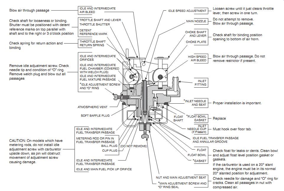
FIG. 33. Developed for Tecumseh carburetors, this illustration has application
for other float-type units.
Loosen screw until it just clears throttle lever, then screw in one turn.
ATMOSPHERIC VENT SOFT BAFFLE PLUG CAUTION: On models which have metering rods, do not install idle adjustment screw with carburetor upside down, as pin will obstruct movement of adjustment screw causing damage.
Blow air through passage Check shaft for looseness or binding.
Shutter must be positioned with detent reference marks on top parallel with shaft and to the right or 3 o'clock position
Check spring for return action and binding Remove idle adjustment screw. Check needle tip and condition of "O" ring.
Remove welch plug and blow out all passages
BALL PLUG CUP PLUG FLOAT SHAFT
Do not attempt to remove.
Blow air through passage.
Check shaft for binding position opening to bottom of air horn.
Blow air through passage. Do not remove restrictor if present.
Proper installation is important.
Replace Must hook over floor tab.
IDLE FUEL TRANSFER PASSAGE AND ANNULAR GROOVE Check float for leaks or dents. Clean bowl and adjust float level position gasket or gaskets.
If the carburetor is used on a 20° slant engine, the engine must be in its normal 20° slanted position for adjustment.
Check needle for damage and "O" ring for cracks. Clean all passages in nut with compressed air.
IDLE SPEED ADJUSTMENT IDLE AND INTERMEDIATE AIR BLEED TROTTLE SHAFT AND LEVER DETENT REFERENCE MARK THROTTLE SHAFT RETURN SPRING IDLE AND INTERMEDIATE ORIFICES IDLE AND INTERMEDIATE FUEL CHAMBER (COVERED WITH WELCH PLUG) IDLE AND INTERMEDIATE FUEL MIXTURE PASSAGE
*IDLE ADJUSTMENT SCREW AND "O" RING IDLE AND INTERMEDIATE FUEL TRANSFER PASSAGE METERING ROD OR PIN IN FUEL TRANSFER PASSAGE IDLE AND MAIN FUEL PICK UP ORIFICE IDLE AND INTERMEDIATE FUEL TRANSFER PASSAGE MAIN NOZZLE CHOKE SHAFT AND LEVER CHOKE PLATE HIGH SPEED AIR BLEED INLET FITTING
*INLET NEEDLE AND SEAT
*FLOAT BOWL GASKET INLET NEEDLE CUP (If Present) FLOAT--FLOAT BOWL
*GASKET NUT AND MAIN ADJUSTMENT SEAT
*MAIN ADJUSTMENT SCREW AND "O" RING SEAL (DO NOT REMOVE) THROTTLE SHUTTER
--------------
Needle and seat
Parking a moped or other gravity-fed engine without turning the fuel tap off encourages flooding, since few inlet needles make a reliable, long-term seal. But most flooding occurs spontaneously, either because the needle sticks in its bore or because a speck of dirt prevents the needle from sealing. This type of flooding can be sometimes corrected with out removing the carburetor from the engine. If no fuel cutoff valve is pre sent, squeeze the flexible fuel hose shut with Vise-Grips. Remove the float bowl and verify that the needle moves freely. Momentarily open the fuel line. The rush of incoming fuel clears the obstruction.
Warning: Allow plenty of the time for the engine to cool before opening the float chamber, work outdoors, well clear of potential ignition sources.
Some carburetors use an assortment of springs and spring clips to cushion needle action. Make careful note of the orientation of these parts. A mistake during assembly can cause the float to hang and the carburetor to flood.
Normally inlet needles and seats are replaced as a matched assembly, together with a new seat gasket. Grind a screwdriver blade to fit the wide slot in the seat and tighten securely. In an emergency, solid steel needles can be lapped to fit with valve-grinding compound and patience. Viton tipped needles are non-repairable.
Viton seats, widely used on American-made carburetors, press into the carburetor inlet fitting. Too little installation force allows fuel to leak around the seat, too much force distorts the needle mating surface. Extract the old seat with a hooked wire and install the replacement part with light hammer taps on a 5/32-in. punch. The crushable, ribbed side of the seat should face down, toward the inlet fitting.
To test for leakage, wet the seat with WD-40 and install the needle and float. Turn the assembly upside down and apply air pressure to the inlet fit ting. The needle should pop off at around 6 psi and hold 1.5 psi for at least 5 minutes. If not, replace the seat.
Floats
The higher the level of fuel in the float chamber, the richer the mixture. Plastic floats have no provision for adjustment, although the mix ture can be leaned slightly by using two gaskets on brass seats. Viton seats offer no opportunity for adjustment. Brass floats have a height adjustment in the form of a tang that bears against the inlet needle.
Float height is determined with the carburetor inverted, so that the weight of the float bears against the inlet needle. Where the measurement is taken varies but most manufacturers express float height as the distance between the inboard edge of the float and the roof of the float chamber. Some would have the cover gasket installed, others do not. Use long-nosed pliers and a small screwdriver to bend the tang. Bending the tang by forcing the float against the needle can distort elastomer seats and needle tips.
Some metallic floats have a second tang that limits drop. Excessive drop makes itself known upon refueling an engine that has run dry. The float pivots downward and, if the angle is excessive, loses enough leverage to bind. The resulting flood is of Biblical proportions. At the other extreme, insufficient drop limits the ability of the carburetor to deliver fuel when tilted off the horizontal.
Instructions accompanying the rebuild kit will include float height and, when appropriate, float drop.
The hollow plastic floats used on American carburetors almost never leak. But sheet-brass floats corrode over time. Test by immersing the float in water that verges on boiling. The heat causes air inside the float to expand. The presence of a leak reveals itself by a trail of bubbles.
Sleeping dogs
Like good doctors, mechanics do not go deeper into disassembly than necessary. Unless the carburetor is extremely dirty or has definite symptoms of stoppage, leave the Welch plugs that cover internal fuel passages in place. The same goes for throttle and choke plates, which have easy-to-strip screws and must be aligned properly upon assembly. If you must remove these parts, scribe mark the outboard sides of the plates and note the position of the choke cutout. Use red Loctite on the hold-down screws.
Tuning
External adjustments-idle rpm, high- and low-speed mixture- are as described for diaphragm carburetors. Err on the side of rich mixtures, since gasoline is cheaper than pistons.
Slide-throttle carburetors
Slide carburetors are used on motorcycles, water craft, and other applications where customers insist upon performance. At WOT, the slide retracts clear of the bore, offering no obstruction to air flow. The slide works in con junction with a tapered needle to vary both air and fuel passing through the instrument, a configuration that smoothes the transition between part- and full-throttle. These features-a fully retractable throttle and a venturi that sizes itself to engine demand-explain why slide carburetors are also known as smooth-bore or variable-venturi carburetors.
Mikuni, Dell'Orto, Bing, Walbro, or Jikov slide-throttle carburetors differ only in detail. Basic features are the same ( Fig. 34). Operation Tbl. 3 provides basic orientation for tuning. But as the following text indicates, there is considerable overlap. For example, the idle jet can continue to flow at full throttle and the shape of the throttle cutaway has a real, but diminishing effect on fuel delivery past half throttle.
Some Mikuni carburetors employ a power jet that can be recognized by the external hose that runs from the float bowl to the air horn.
Cruise and high-speed
At 1/4 to 3/4 throttle, the clearance between the needle and needle jet controls fuel delivery with some assistance from the air bled and the cutaway milled on the leading edge of the slide. A clip secures the grooved needle to the slide. Raising the needle richens the mixture by increasing flow through the needle jet. One can also experiment with needle jet size and, when available, different needle tapers. Mikuni, the premier manufacturer of these carburetors, offers a range of slide cutouts that influence the amount of vacuum acting on the needle jet at partial throttle and air jets of different orifice diameters.
Beyond 3/4 throttle, the needle retracts out of its jet and fuel delivery becomes progressively more dependent upon the size of the main jet, as modulated by the air bleed. When changing main jets, protect the engine by working one size at a time from over-rich towards lean.
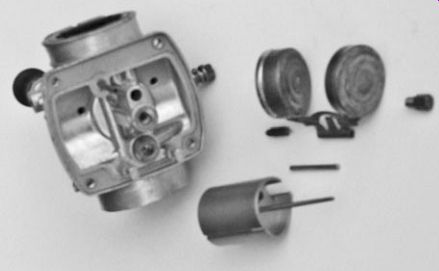
FIG. 34. The throttle consists of a tubular slide with a cutaway on the leading
edge. The needle moves with the slide to vary fuel delivery in concert with
air flow.
A "pontoon" float is pretty well standard, in the tradition of early Amal units.
----------
Tbl. 3 Major influences on mixture strength by throttle position
Throttle opening Major influence on mixture 0-1/4
Idle jet 1/8-1/2
Throttle cutaway 1/4-3/4
Needle position 3/4-full power
Main jet diameter 1/2-full power
Power jet
-----------
Low speed
Air flow past the nearly closed slide does not generate sufficient vacuum for the needle jet to flow at between 0 and 1/4 throttle. Fuel enters the carburetor bore through the idle, or pilot, jet and enters the main bore through the idle discharge port, located just aft of the slide valve. While single-port models are encountered, most carburetors have a second, off idle port that comes into play as the throttle cracks open wider. Fuel under goes aeration prior to discharge. The pilot air screw works in conjunction with the low-speed jet to meter fuel. The low-speed circuit remains active across the rpm band on Mikuni-pattern carburetors.
Note that air adjustment screws work in reverse of fuel adjustment screws. Tightening an air screw reduces air flow to richen the mixture.
Of-idle hesitation suggests that the pilot jet is plugged or that the air adjustment screw is too far backed out.
FIG. 35. Raising the brass plunger (shown at the upper right of the photo)
activates the starting jet on Mikuni-pattern carburetors.
Cold enrichment
As used on Mikuni carburetors and their clones, the cold-enrichment circuit works in conjunction with a lever-operated plunger and a closed throttle to deliver a rich mixture for starting ( Fig. 35). Intake vacuum draws fuel from the bowl, which then passes through the starting jet into a small mixing chamber for aeration. Raising the brass plunger uncovers the discharge port and fuel, impelled by intake-pipe vacuum, enters the main bore at a point just downstream of the slide. Opening the throttle closes the plunger.
External adjustments-diaphragm and float-type carburetors
Depending upon the application, model, and build date, carburetors have as many as four external adjustments: the throttle-cable anchor, idle rpm screw, and low- and high-speed mixture adjustment needles. The throttle cable anchor is found on chainsaws and other handheld tools with remote throttle triggers. Adjust to allow some free play in the cable when the trigger is released. At full speed, the throttle should open fully.
The idle rpm screw, also known as the idle stop screw or idle adjustment screw, determines how far the throttle remains cracked at idle. Normally, the factory setting suffices. If the screw has been disturbed, set the idle to factory specifications. Most handheld equipment idle on the upside of 2000 rpm or just under clutch-engagement rpm. Motorbikes and outboard motors can idle a bit slower, but few two-strokes are happy below 1000 rpm.
You might want to invest in a small-engine tachometer, such as the Vibratach, available from Briggs & Stratton dealers for around $40. The German-made instrument senses rpm as the vibration of an extendable wire. Set rpm on the dial, hold the instrument against the engine, and watch as the wire goes into harmonic vibration. There are also a number of electronic tachometers on the market that work from ignition voltage pulses.
Pre-emission carburetors have both low- and high-speed adjustment needles or as they are sometimes called, screws ( Fig. 36). These needles are spring-loaded to hold adjustment and may make up against O-rings.
The low-speed needle controls the amount of fuel flowing through the idle and transition ports. Turning the needle counterclockwise richens the mixture. The high-speed needle does the same for the main jet. Some manufacturers mark needles "L" and "H," but the location of the needle identifies its function. The needle closest to the engine controls the low-speed mixture.
The high-speed needle, whether on the carburetor body, under the float bowl, or behind the air filter, is always upstream of the low-speed needle.
Take a close look at the needles: a visible groove on the tip is normal, but a bent tip or a groove deep enough to hang a thumbnail means that the needle should be replaced. This sort of damage results from forcing needles hard against their seats. Finger-tight is tight enough. A really ham-fisted mechanic can run the needles in far enough to distort the seats. The effect is to make mixtures ultra-sensitive to needle position. Tuning becomes a knife-edged proposition.
-------------
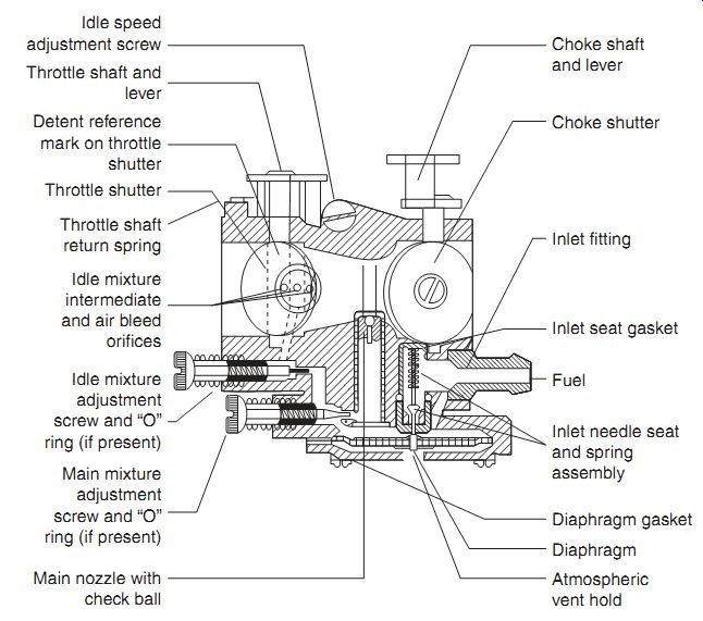
FIG. 36. Tecumseh low- and high-speed adjustment needles do not interchange.
Choke shutter Choke shaft and lever Inlet fitting Inlet seat gasket Fuel Diaphragm gasket Diaphragm Atmospheric vent hold Main nozzle with check ball Main mixture adjustment screw and "O" ring (if present) Idle mixture adjustment screw and "O" ring (if present) Idle mixture intermediate and air bleed orifices Throttle shaft return spring Throttle shutter Idle speed adjustment screw Throttle shaft and lever Detent reference mark on throttle shutter Inlet needle seat and spring assembly
-------------
In order to meet emissions requirements, manufacturers put restraints on mixture adjustments. Most modern carburetors have fixed high-speed jets and fence off low-speed needles behind anti-tampering caps or other kinds of travel limiters. Do not defeat mixture limiters. The EPA has authority to impose a $10,000 fine for modifications that increase emissions of handheld equipment manufactured since 1996.
When emissions are of no concern, carburetor adjustment is a matter of tuning for best power. Adjust the high-speed mixture to the threshold of four-stroking, that is, when the engine skips one or two beats and fires with a bang. Rich mixtures of this kind do no harm to the engine, but can overheat catalytic converters. Lean mixtures are fatal.
The procedure that follows assumes that the carburetor has both low- and high-speed adjustment needles with a full range of travel.
• Start the engine and allow it to reach normal operating temperature.
• Begin with the low-speed adjustment. Turn the needle clockwise in small increments, about an eighth of turn at a time. Allow few seconds for the effect of each adjustment to be felt. Stop when engine rpm drops off at the lean limit. Note the position of the screw slot.
• Back off the needle in small increments as before. Continue to richen the mixture until engine speed falters at the rich drop-off point. Again, note the position of the screw slot.
• The final adjustment is halfway between lean and rich drop-off points.
Caution: Run lean only as long as necessary to detect the drop-off point.
Prolonged lean operation will fry the piston.
• Adjust the idle rpm screw to the specified speed or just below clutch engagement speed.
• With the throttle three-quarters open, repeat the process for the high speed needle. Set the needle at the midpoint between lean and rich drop-off points. When in doubt, err on the rich side.
Note: Some Tecumseh and Walbro carburetors limit rpm with a governor that complicates the high-speed adjustment. See the "Governor" section above for further information.
• Snap the throttle open from idle. The engine should accelerate almost instantaneously. Stumble, hesitation, or flat spots call for a richer mixture. Most carburetors respond to a slightly richer low-speed mix ture, others accelerate more smoothly if the high-speed mixture is richened. Experiment until you find the correct combination.
• Test the engine under load, richening the mixture as necessary.
• To further verify the adjustment, run the engine under normal loads for a half-hour or so, shut off the ignition with the throttle open, and read the spark plug as described in the Section 2.
A last word
One can become lost in the complexity of fuel systems, especially when dealing with late-model diaphragm carburetors. Remember that diaphragms cause most problems, followed by inlet needles and seats.
Float-type carburetors give relatively little trouble. Inlet needles and seats are the main culprit, followed by main jets mounted low in the float bowl, where they collect residue and clog.
All carburetors are sensitive to dirty or aged fuel that clogs main jets, inlet screens, and low-speed circuits. Older carburetors can be stripped of their soft parts and immersed in carburetor cleaner for a half hour or so. Many newer carburetors have non-removable plastic parts. For these units, a quick dunk in an immersion-type cleaner is a last option, when all else has failed.
Fuel pumps, whether integral with the carburetor or stand-alone units, require periodic diaphragm replacement. Pumps also malfunction if the crankcase pulse port clogs or if work-hardened plastic lines leak air.
And finally, reading about carburetors is not the same as fixing them. Words, pictures, and troubleshooting charts fall short of the reality. The only way to come to terms with these recalcitrant devices is through the experience of working with them. And if you do much of this work, you will encounter an outlaw, a carburetor that refuses to conform to what we think are the rules.
I remember a Harley that ran lean at high speeds, even after drilling main jet oversized.
Prev. | Next
Home Article
index top
of page