Any small-engine ignition, even the most primitive Wico magneto, can generate the 12 kV needed to fire a clean spark plug. But none of these systems deliver the voltage needed to fire dirty plugs or ignite less-than-optimum air fuel mixtures. This is why small engines are so susceptible to flooding and why spark plugs need such frequent replacement.
Automotive ignitions put out about 40 kV and the spark plugs are gapped accordingly, with 0.050 in. as the norm. No small-engine spark plugs are gapped more than 0.025 in. and many run as narrow as 0.008 in.
More voltage would make starting easier and, in combination with a wider spark gap, would smooth combustion. In-cylinder mixtures are not homogeneous; in some areas the mixture is too lean to ignite or, when ignited, burns slowly. The pressure rise in the cylinder becomes erratic, as if ignition timing were wandering. A wide spark gap betters the odds of encountering a rich, combustion-prone mixture.
That said, we pretty much have to live with OEM ignition systems. About all that one can do is to keep several spark plugs on hand and accept that small engines are prone to flooding. Once this happens, stop cranking, let the machine sit for half an hour, and it usually will start.
It is possible to update transistorized and point-and-condenser magnetos with capacitive discharge (CD) modules, but the exercise would be prohibitive for anyone who does not have a stock of used parts. It is also possible to install a modern automotive ignition system. Brian Miller (http://gardentrac torpullingtips.com/a1elect.htm) can supply the parts and the expertise. The conversion requires a 12V source of voltage, which can be a problem. MSD also makes a battery-powered capacitive discharge ignition (CDI) for small engines, but for reasons that are not clear, limits applications to four-strokes.
Diagnosis
Solid-state ignition modules behave like light bulbs. That is, they usually work fine until complete failure. Old-time magnetos often failed by degrees as con tact points oxidized and became resistive.
As pointed out in the previous section, open sparks and a gasoline engine are not a good combination. Some gasoline vapor will be present, especially if the test is done with the spark plug removed from the cylinder. Several factory ignition testers eliminate the hazard by confining the spark behind a transparent window.
Occasionally one encounters an engine with a misfire that no amount of carburetor work will cure. In these cases, it can be helpful to monitor spark output with an automotive timing light. The new Xenon lights with a self contained power source are ideal for small-engine work; otherwise, the light must be powered. Power the light with a 12V auto battery. If you run across an old-fashioned neon timing light in a garage sale, buy it. These lights seem to last forever and require no external power source.
Once you have determined that the ignition is at fault, isolate the ignition module from other wiring. At the minimum, a wire from the primary side of the ignition module goes to kill switch. Verify that the switch is normally open and not grounded to the engine. You can do this with an ohmmeter, or simply by testing for spark with the switch disconnected from the ignition module.
Flywheel
If there is no or weak spark, remove the flywheel in order to check the condition of the key, which fixes the timing between flywheel magnets and the ignition coil. Keys shear or deform in response to sudden loads or as the result of insufficient torque on the flywheel hold-down nut ( Fig. 1).
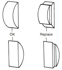
FIG. 1. A distorted or sheared flywheel key is a major cause of ignition
problems.
The flywheel secures to the crankshaft with a taper, a nut and lock washer.
The nut has a conventional right-hand thread 99.9% of the time. Unless you have access to an impact wrench, the flywheel must be prevented from moving as the nut is loosened. Hold the wheel with a strap wrench or lock the piston with a length of nylon rope fed into the cylinder through the spark-plug port. ( Fig. 2)
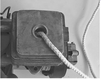
FIG. 2. The old rope trick.
The flywheel and crankshaft interfaces are tapered, which means that an ordinary gear puller cannot be used. Many flywheels are drilled and tapped for a hub puller as shown in Fig. 3. A steering-wheel puller, available from auto parts stores, will usually substitute for the factory tool. You will, however, need metric bolts (usually 6 mm × 1.0) for attachment to the hub.
Flywheels for small motorcycles often have internal hub threads for which suitable pullers are difficult to find. If the dealer is of no help, try looking for a suitable tool in upscale bicycle shops. Otherwise, a metric-threaded puller will have to be machined.
Flywheels with no provision for puller engagement must be shocked off.
The preferred tool is a fairly heavy steel bar with threads that match those on crankshaft. Knockers can, at least for now, be purchased from Tecumseh dealers as PN 570105 for right-handed 1/2-in. × 20 threads and PN 670169 for 7/16-in shafts. Metric knockers must be fabricated, which can be done easily on a lathe or more laboriously with a portable drill and the appropriate tap.
Figure 4 illustrates the use of a knocker. Wear eye protection, run the knocker down to within two or three threads of the flywheel, and strike hard enough to compress the crankshaft taper. Prying up on the underside of the wheel with a screwdriver assists removal. Be careful where you place the screwdriver when the ignition coil lives under the flywheel. If removing the flywheel in this manner causes the crankshaft to bind, restore main-bearing float by driving the crank upward with a soft mallet ( Fig. 5).
Ball bearing
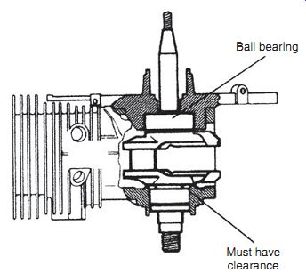
FIG. 5. If the crankshaft binds after shocking the flywheel loose, the main
bearings have been unseated. Restore bearing float with a sharp blow from a
mallet on the pto (power takeoff) end of the crankshaft.
An even more brutal approach is to knock the flywheel off with a hammer and brass bar. Back the flywheel nut out to shield the threads.
Most engine makers reference the flywheel to the crank with a removable key. Poulan and others cast the key as part of the aluminum hub ( Fig. 6). If the key shears, the easiest recourse is to purchase a new flywheel. But fly wheels are expensive, and you may want to file a keyway into the hub, using the mark left by the sheared key as the reference. Cutting an internal keyway by hand sounds primitive, but was standard practice throughout most of the nineteenth century. Hardware stores carry key stock that can be filed to fit.
Another, and less reliable, approach is to forget about the key, which is merely an assembly reference. Coat the crankshaft taper with red Loctite, align the keyways, and tighten the hold-down nut.
Warning: Always replace a cracked or otherwise damaged flywheel.
Cracks, most of which originate at the keyway, grow slowly until they reach critical length. When that happens, the flywheel explodes.
Assemble the flywheel and crankshaft tapers dry, since the effectiveness of the connection depends upon friction. Although small-engine manufacturers are coy about this, automotive practice calls for torqued threads to be lubricated with 30W motor oil. Broadly speaking, the flywheel nut on mini-motors, those that displace between 22 and 50 cc, requires about 175 in./lb of torque.
A reasonable figure for engines in the 80 to 100-cc class is 275 in./lb. Contact your dealer for the exact specification.
Warning: Do not tighten flywheel nuts with an impact wrench. Over torquing can crack the hub.
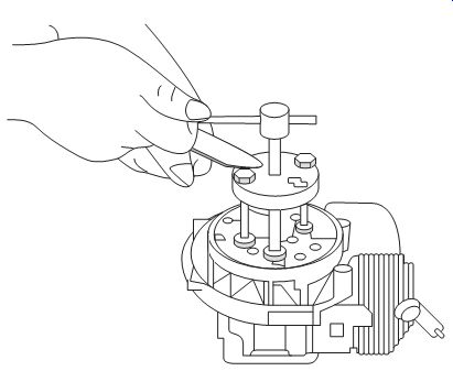
FIG. 3. Tanaka and other professional-quality products have their flywheel
drilled and tapped for hub pullers. Hitachi Koki USA
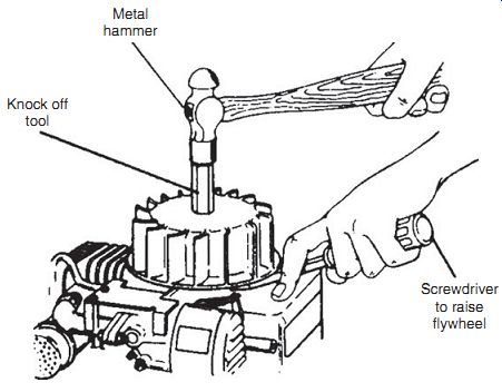
FIG. 4. Knocking a flywheel off can result in a broken crankshaft, brinelled
main bearings, and scrambled flywheel magnets. But millions of engines have
been abused in this manner without such catastrophic effects.
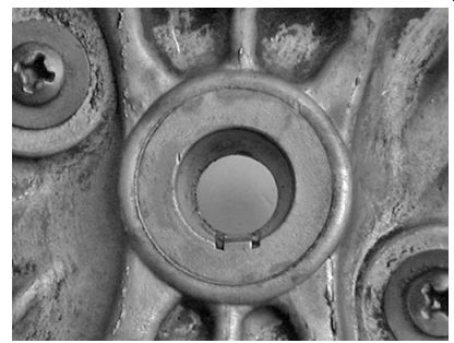
FIG. 6. Flywheels with stripped cast-in keys can be salvaged with a suitable
file and patience.
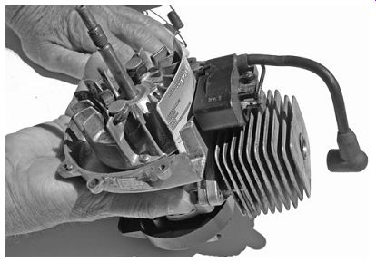
FIG. 7. An external ignition coil simplifies E-gap adjustment. Nearly all
under-flywheel coils have an adjustment provision by way of a window in the
flywheel. Those few that don't can be set by temporarily applying a single
layer of friction tape over the ends of the coil armature. The correct E-gap
generates a slight, but perceptible, drag on the tape as the flywheel is turned.
E-gap
All engines have provision for adjusting the E-gap, or the distance ignition-coil armature stands off from flywheel rim. The narrower the gap, the stronger the magnetic field and the greater the voltage produced by the coil. Ideally, the gap should approach zero, but we must allow for bearing play, thermal expansion, and flywheel out-of-round. An E-gap of 0.012 to 0.014 in. is sufficient. Skid marks on the flywheel rim from contact with the coil armature mean that the gap is too narrow or that the crankshaft is bent.
The adjustment procedure goes as follows:
1. Rotate the flywheel to bring the magnets adjacent to the armature.
2. Insert the appropriate gauge between the flywheel and coil armature.
A nonmagnetic feeler gauge would be the best choice, although many mechanics use a business card ( Fig. 7).
3. Loosen the coil hold-down screws. The magnets will draw the coil into specification.
4. Tighten the screws and rotate the gauge free.
Magnetos
Ignition and generating systems depend upon the interplay between magnetic lines of force, or flux, and electricity. This interplay can be described as follows:
• Electricity is generated in a conductor when magnetic lines of force move through a conductor. The faster the movement, the greater the electrical potential generated. To make things more efficient, the conductor consists of a coil of copper wire wrapped over a laminated iron core. Iron acts as a lens to focus magnetic flux.
• The reverse also holds, that is, current flow generates magnetic lines of force at right angles to the conductor. An ignition coil consists of two windings. The primary winding, made up of several hundred turns of heavy wire, goes on next to the armature. The secondary winding, consisting of 10,000 or more turns of superfine wire, wraps over the primary windings, so that it is saturated with the magnetic lines of force created by current flow in the primary.
• The ratio of primary to secondary windings determines the voltage gain. Thus, if the primary consists of 200 turns and the secondary 10,000 turns, the voltage in the secondary would theoretically increase (10,000/200) 500 times. In practice, the gain is somewhat less.
A magneto generates voltage in the primary by virtue of the moving fly wheel magnet. One end of the winding grounds to the engine frame; the other end connects to a switch that, when closed, also grounds to the engine. While the classic magneto used contact points as the switch, more modern designs employ a solid-state switch. When the switch closes, the primary circuit is completed through engine grounds and current flows.
The grounding provision for the secondary is similar, in that one end of the winding permanently grounds to the engine and the other end terminates at the spark plug. Once sufficient voltage is present, the secondary circuit completes itself to ground by discharging across the spark-plug gap.
In order to induce the high voltage necessary for ignition, magnetic lines of force must move far more rapidly than afforded by the velocity of the flywheel rim. How a magneto achieves this is a tribute to human ingenuity.
Two mechanisms are involved: flux reversal and flux collapse.
Flux reversal accounts for the distinctive E-shape of the magneto armatures. Lines of force flow from the magnetic north pole to the south pole.
As you can see in Fig. 8, the initial movement is up through the center leg of the armature and down to the south pole through the trailing leg.
As the flywheel continues to turn, the north pole comes into proximity with the leading leg of the armature. Seeking the south pole, magnetic lines of force now move downward in the center leg ( Fig. 9). Movement is reversed, which means that lines of force have momentarily halted and accelerated in the opposite direction.
At the peak of magnetic activity caused by flux reversal, the switch that controls the primary circuit opens. Current, now denied ground, no longer flows in the primary windings. The magnetic field that accompanied current flow collapses in on itself at light speed. Secondary voltage increases until the spark plug resolves the tension by firing.
Magnetos with contact points
Vintage magnetos employed a mechanical switch, called the contact points, point set, or breaker points, to turn primary current on and off. Some Honda four-strokes still use this archaic form of ignition.
One of the contacts is fixed and permanently grounded to the engine. The moveable contact forms part of the primary circuit. When the points are closed, the primary circuit completes to ground. At about 20° of crankshaft rotation before top dead center (TDC), the moveable contact cams open, or breaks, to initiate ignition. A condenser (the obsolete term for "capacitor") absorbs electrical energy that would otherwise appear as sparking across the point contacts.
Mechanical switches, especially switches that cycle once every crankshaft revolution, are inherently unreliable. The rubbing block that bears against the cam wears, throwing the points out of adjustment, and the tungsten contacts oxidize and pit. In order to provide a reasonable life, primary current must be limited to something less than 3 A. This limitation results in a low energy spark, especially during cranking.
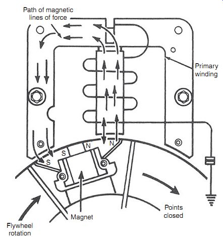
FIG. 8. The center leg is a two-way street for lines of magnetic force. Initially
movement is up through the center leg and down through the trailing leg. Points
are closed at this time.
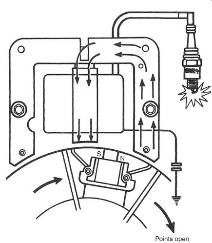
FIG. 9. A few degrees of additional flywheel movement cause a sudden reversal
in flux direction through the center leg. The points open and the spark plug
fires.
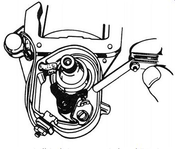
FIG. 10. Wipe any oil off the feeler gauge and, if you follow the procedure
favored by many mechanics, adjust the gap by bracketing. A 0.020-in. gap is
indicated when a 0.019-in. blade slips easily between the contacts and a 0.021-in.
blade generates perceptible drag. The blade must, of course, be held parallel
to the contacts.
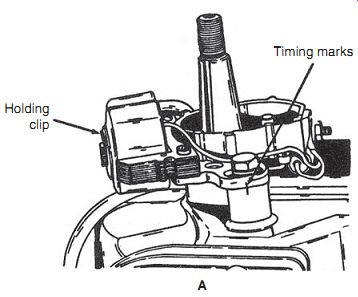
FIG. 11. Phelon magnetos of the type found on American utility engines have
timing marks as an assembly convenience (A). High-performance engines should
be timed with a dial indicator, such as the Tecumseh PN 670241 (B). The piston
is brought up to top dead center, the indicator zeroed, and the flywheel turned
until the piston (which should be free of carbon deposits) is at the specified
distance before TDC. Timing is correct when turning the magneto stator against
the direction of engine rotation just cracks the points open. An ohmmeter with
one test lead clamped to the moveable contact arm and the other grounded gives
an accurate indication of point break. A piece of cigarette paper inserted
between the closed contacts can also be used to detect point separation.
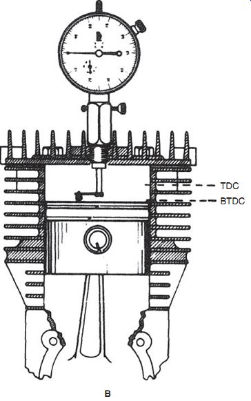
FIG. 11. (Continued)
Magneto service
As with any ignition system, begin by changing out the spark plug and, if that doesn't help, lift the flywheel to inspect the key. Replace points and condenser as a matter of course. All small-engine magnetos that the writer is aware of function with the point gap set at 0.020 in., although some magnetos seem to perform better at 0.017 or 0.018 in. Follow this procedure:
1. Disconnect the condenser and point set from the primary winding.
Note the lay of the parts.
2. A small screw and one or more locating pins secure the point set to the magneto stator plate. If two screws are present, one is an eccentric that varies the gap between the moveable and fixed contacts.
3. Remove all traces of oil from the stator to provide a clean ground for the new parts.
4. Install the new point set and condenser. Owners of vintage engines may find that these sacrificial parts are in short supply. Any point set that can be modified to fit and any ignition condenser will work.
5. Turn the crankshaft so that the point cams fully open ( Fig. 10). The hold-down screw will have to be lightly snugged down to prevent the point spring from closing the points. Now bring the moveable point to within 0.020 in. of the fixed point. Breaker sets without an adjustment screw are slotted for screwdriver access.
6. Test for spark. In event of no spark, burnish the contacts with a business card and retest. Tungsten contacts oxidize in storage and have zero tolerance for oil, even the oil left by a fingerprint.
7. If a new condenser and new, properly adjusted, and clean points fail to restore spark, replace the coil.
Timing
Magnetos for light motorcycles, outboard motors, and some utility engines have provision for timing adjustment ( Fig. 11). Transistorized ignition Much to the relief of mechanics everywhere, transistorized ignition (TSI) has become nearly universal. Transistorized magnetos substitute a Darlington transistor (actually a pair of transistors) for the contact points and condenser.
Doing away with these troublesome components was the best thing that happened to small engines since the advent of loop scavenging.
On the downside, these TSI systems are non-repairable. If something goes wrong, replacement is the only option. Nor can TSI be easily adapted to earlier engines without the availability of factory parts. The trigger coil requires a dedicated flywheel magnet.
Capacitive discharge ignition
As the twentieth century drew to a close, transistorized magnetos gave way to capacitive discharge ignition (CDI) systems. As the name suggests, CDIs store electrical energy in a capacitor, which then discharges into the primary windings of an ignition transformer.
Figure 12 illustrates the basic circuit. A flywheel magnet generates several hundred volts in the charge coil that is then rectified (i.e., converted from AC to DC) by diodes D1 and D2, and stored in the capacitor (C1). The silicon-controlled rectifier (SCR) initially acts as a check valve to permit cur rent flow into the capacitor and block flow out of it. Further rotation of the flywheel causes the trigger coil to generate a signal voltage across resistor (R1).
This voltage sends the SCR conductive. Seeking ground, electrons stored in the capacitor flow into the primary side of the ignition coil, or as it’s commonly termed the pulse transformer. The expanding magnetic field that accompanies the influx of current induces a sudden spurt of high voltage in the transformer secondary winding. This voltage goes to ground through the spark plug.
The voltage rise in the secondary windings of point-controlled magnetos averages about 50 V/µs (millionths of a second). Transistorized magnetos do a bit better at 80 V/µs. CDIs build voltage almost instantaneously at rates of between 3 kV and 10 kV/µs. Confronted with these sudden bursts of voltage, dirty spark plugs fire before they have time to leak to ground. CDI makes starting easier, especially for two-stroke engines.
On the debit side, CDI voltage disappears almost as quickly as it is generated. Burn time-spark duration-ranges from 50 to 80 µs. In comparison, transistorized ignitions have burn times of between 500 µs and 0.001 second.
Consequently, a CDI can fail to reliably ignite lean mixtures. MSD, Mallory, and other high-performance automotive CDIs minimize the problem by generating multiple sparks at speeds below 3000 rpm. Small-engine units do not, at present, have this capability.
TSI and CDI systems require resistance-type spark plugs, if your neighbors are going to talk on cell phones or watch television.
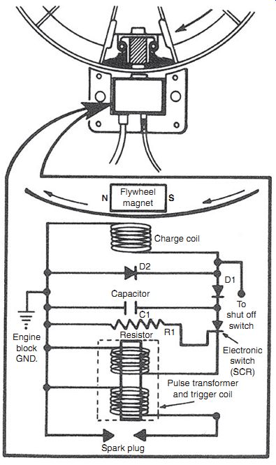
FIG. 12. Tecumseh CDI circuitry is typical, although some battery-operated
systems include diodes to protect components from reversed polarity.
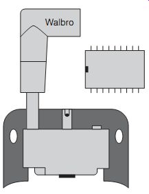
FIG. 13. Walbro digital CDI.
Digital CDI
Solid-state systems have some built-in ignition advance by virtue of flywheel velocity. As rpm increases, signal voltage occurs earlier, since the flux field moves faster. But advance is linear and not tailored to engine characteristics.
Digital control retards ignition during cranking to prevent starter-cord "bite" and advances timing in a patterned sequence that can be modified by the engine maker ( Fig. 13). The integrated circuit (IC) also acts as governor, retarding timing as the preset rpm limit is approached. Digital control costs almost nothing at the OEM level: one company offers IC timing controllers for 39 cents each in batches of 10,000. But like other solid-state components, digital CDIs are non-repairable and non-testable. If you suspect that something is wrong, say, that the timing has gone haywire, the only recourse is to spring for a new module.
Spark plugs
Now that leaded fuel is no more, spark plugs can be cleaned by soaking in carburetor cleaner. Sandblasting is out of the question, since the abrasive particles imbed themselves in the insulator where they fall into the cylinder once the engine starts.
In passing, it should be mentioned that the jagged, blackish discoloration on the outside of the insulator just below the rubber boot has no effect upon performance. It is caused by the same corona effect that makes high-voltage power lines glow.
The center electrode rounds off in service, increasing the voltage requirement. Ordinary carbon steel or copper electrodes can be dressed with a point file. This does not apply to exotic plugs sometimes used in high-output engines. These plugs are characterized by small-diameter center electrodes that, in order to provide useful life, are capped with precious metals. Filing merely removes the gold, platinum, silver, or yttrium coating. Champion iridium electrodes can be filed, since the whole electrode is made of this refractory material.
Traditional spark plugs are best gapped with a cam-type gauge as illustrated back in Fig. 2. Precious-metal plugs generally come pre-gapped, but can be set to the exact specification if the vulnerable center electrode does not see any bending force. In other words, confine the bending to the side electrode by using long-nosed pliers or a small bending bar, drilled to slip over the side electrode.
Remove all traces of grease and oil from the gasket surface (aerosol brake cleaner and Q-tips work) and run the spark plug in by hand for at least three full turns. Torque to specification 10 mm 7.2-8.7 ft/lb 12 mm 10.8-14.5 ft/lb 14 mm 18.0-21.6 ft/lb
While some mechanics like to use antiseize compound on outboards and other engines exposed to weather, these lubricants reduce friction enough to result in over-torquing. Silicon, because of its poor lubricating characteristics, is a good compromise.
Heat range
Heat range depends primarily upon the exposure of the insulator to combustion heat. As shown in Fig. 14, the greater the exposure and the longer the thermal path, the hotter the plug. The plug should run hot enough to pre vent fouling, but not so hot that it ignites the mixture early, before the spark ( Fig. 15). Should this happen, the engine self-destructs.
Manufacturers describe heat ranges numerically. For domestic spark plugs, the higher the number, the hotter the plug. Thus, a Champion J19LM is hotter than a J17LM. Foreign manufacturers usually, but not always, assign higher numbers to colder plugs. At the first sign of trouble, replace the spark plug with the same type and, whenever possible, with the same brand specified in the owner's manual. Interchange guides list physically equivalent plugs, but heat ranges vary somewhat between manufacturers.
Matching spark plugs to the needs of racing and other high performance engines is beyond the scope of this guide. Plenty of this information is avail able elsewhere. But more prosaic engines sometimes come without documentation and one needs to select a spark plug that will do no damage.
Begin with a cold plug and run the engine under normal work loads for an hour or so, adjusting the carburetor for best power. If the plug blackens and fouls, go hotter one heat range. Continue a step at time with spark plugs from the same manufacturer until the insulator takes on a dark brown color, indicating that temperatures are normal. Err on the side of cold (dark), since the worst that a cold plug can do is foul.
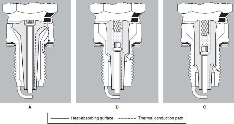
FIG. 14. The shape of the insulator tells the story. A hot plug exposes a
large surface of the insulator to combustion heat that must travel high into
the barrel to find release (A). The insulator for a cooler plug has less exposure
and provides a shorter thermal path (B).
The coldest plug has the smallest insulator nose (C). Bosch
Thread repair
Over-torquing or cross-threading strips the threads on aluminum cylinder heads. With the right tools, one can salvage the head with a Heli-Coil or equivalent insert. Unfortunately, the cost of the installation tools is prohibitive for weekend mechanics, who may see a stripped head once in a lifetime.
Spark-plug thread repair kits are specific to each thread diameter and cost $130 or more. Small-engine dealers invoke a daunting minimum labor charge for this 5-minute job. The best chance of obtaining an economical repair is at an old-fashioned auto parts house that does machine work on the side.
Summary
A new spark plug cures most ignition problems. Other likely suspects are a damaged flywheel key or fretted insulation on the wire to the kill switch. As a last resort, replace the solid-state ignition module. The tungsten points used in vintage magnetos are an endless source of trouble. The point gap narrows as the rubbing block wears and the contacts become increasingly resistive in service. "New old-stock" point sets, which have languished on dealer shelves for decades, can be restored to service by burnishing the contacts with a business card. If you cannot find the correct replacement con denser, substitute an automotive unit.
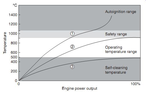
FIG. 15. A spark plug with the correct heat range (2) walks the narrow line
between fouling and autoignition.
Prev. | Next
Home Article
index top
of page